JVC GY-DV500E Instruction Manual - Page 13
-Inch Viewfinder optional, Lens optional
 |
View all JVC GY-DV500E manuals
Add to My Manuals
Save this manual to your list of manuals |
Page 13 highlights
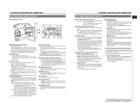
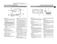
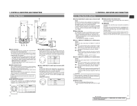
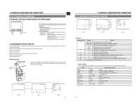
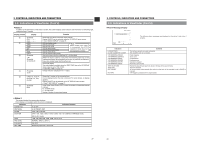
2. CONTROLS, INDICATORS AND CONNECTORS 2-7 Lens (optional) [S14 x 7.3B12] ew q RET M A W T r t y ui o !0 !4 MACRO 1 FOCUS ring Manual focus ring. !1 !2 !3 2 ZOOM lever/ring This is the manual zoom ring equipped with a zoom lever. To adjust the zoom manually, turn the zoom mode knob @ to position "M". 3 IRIS ring Manual iris ring. To activate the auto iris feature, set the Iris Mode switch 7 to A. 4 [VTR] Trigger button To start/stop shooting. 5 [RET] return video button The return video signal from the VCR section can be monitored in the viewfinder only while this button is pushed. * The playback picture can be viewed in the viewfinder during this operation. 6 ZOOM servo control lever To operate the servo zoom feature with this lever, set the ZOOM knob @ to S. • Pressing the W section of this lever increases the angle of the lens for a wider shooting angle. • Pressing the T section of this lever narrows the lens angle perspective for telephoto shots. • Pushing harder changes the speed of the zoom. 24 7 IRIS mode switch A: Activates the auto iris feature. M: Allows manual iris control. 8 Momentary auto iris button When the IRIS MODE switch 7 is at "M", pushing this button activates the Auto Iris Function while it is held down only. 9 [S] IRIS speed adjusting control For adjusting the iris operation speed. Memo: If the speed becomes too fast, hunting may occur. • To avoid the phenomena described above, perform adjustment again. 0 FILTER thread Protect the lens with a clear filter or UV filter by screwing the filter onto the thread inside the lens hood from the front. Other filters can be used for various effects. CAUTION: The filter thread section rotates, so pay attention when mounting a polarizing filter. ! ZOOM servo connector Connect an optional zoom servo unit here. @ ZOOM mode knob S: Servo zoom mode. Allows operation by the zoom servo control lever 6. M: Manual zoom mode. Allows zoom control by the zoom lever/ring 2. # BACK FOCUS ring/fixing screw For back focus adjustment only. Secure with the screw knob after adjustment. See "Back Focus Adjustment" on page 44. $ Macro focusing ring (for close-up shooting) By rotating this ring in the direction of the arrow, close-up shooting of very small objects becomes possible. Normal focus adjustment and zooming are not available in the macro mode. To shoot images in the macro mode, set the focus ring 1 to the infinite position and the zoom ring 2 to the maximum wide-angle position. To adjust the focus of the macro image, rotate this ring in the direction of the arrow until the object is focused. CAUTION: • The back-focus knob is located close to the macro ring, be careful not to mistake the back-focus knob for the macro ring. • After the required operation, be sure to return the macro focusing ring to the normal position. See "Attaching the Zoom Lens (optional)" on page 31. See "Back Focus Adjustment" on page 44. 23 2. CONTROLS, INDICATORS AND CONNECTORS 2-8 1.5-Inch Viewfinder (optional) [VF-P115B] 4 5 1 Stopper screw This screw prevents the viewfinder from coming off the camera. 6 2 Mounting guide To attach on the camera. 3 Connector Connect to the camera. 4 [CONT] contrast adjustment To adjust the contours of the viewfinder image. 1 5 [BRIGHT] brightness adjustment To adjust the brightness of the viewfinder. 6 [TALLY] switch Set this switch to OFF to prevent the tally light 7 from turning 2 on and informing people that they are being recorded. However, the REC indicator lamp in the eyepiece will not 3 turn off. 7 Tally light Lights when recording is in progress. To prevent this light from coming on, set the tally switch 6 to "OFF". 8 Eyepiece Ensures that ambient light does not reach the viewfinder screen or falls into the eye of the cameraman. The eyepiece can be opened to allow direct observation of the viewfinder screen. 9 Eyepiece focusing ring Loosen this ring to move the eyepiece back or forth to adjust the diopter. 7 8 9 24 25
-
 1
1 -
2
-
3
-
4
-
5
-
6
-
7
-
 8
8 -
 9
9 -
 10
10 -
 11
11 -
 12
12 -
 13
13 -
 14
14 -
 15
15 -
 16
16 -
 17
17 -
 18
18 -
19
-
20
-
21
-
22
-
23
-
24
-
25
-
26
-
27
-
28
-
29
-
30
-
31
-
32
-
33
-
34
-
35
-
36
-
37
-
38
-
39
-
40
-
41
-
42
-
43
-
44
-
45
-
46
-
47
-
48
 |
 |
