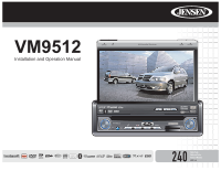
Jensen VM9512 Operation Manual - Page 6
Optional Equipment, Tools and Supplies, Disconnecting the Battery - wiring
 |
UPC - 043258303783
View all Jensen VM9512 manuals
Add to My Manuals
Save this manual to your list of manuals |
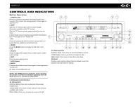
Page 6 highlights
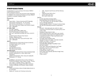
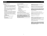
VM9512 Optional Equipment • NAV101 The VM9512 is "navigation ready." Before accessing any navigation features, you must purchase and install the NAV101 module. All installation and operating instructions will be included with the NAV101 navigation module. Once the NAV101 is connected and operating properly, the NAV source mode will become active. While the NAV101 is not installed, the NAV option appears gray, indicating the function is not available. • Rear Camera The VM9512 is "camera ready." Before accessing any camera features, you must purchase and install a rear video camera. Once the rear camera is connected and operating properly, the CAMERA source mode will become active. While the camera is not installed, the CAMERA option appears gray, indicating the function is not available. • Satellite Radio Tuner See "Satellite Radio Operation" on page 22. • iPod See "MP3/WMA Operation" on page 29. • Bluetooth Phone See "Bluetooth Operation" on page 32. Tools and Supplies You will need these tools and supplies to install your VM9512: • Torx type, flat-head and Philips screwdrivers • Wire cutters and strippers • Tools to remove existing radio (screwdriver, socket wrench set or other tools) • Electrical tape • Crimping tool • Volt meter/test light • Crimp connections • 18 gauge wire for power connections • 16 - 18 gauge speaker wire Disconnecting the Battery To prevent a short circuit, be sure to turn off the ignition and remove the negative (-) battery cable prior to installation. NOTE: If the VM9512 is to be installed in a car equipped with an on-board drive or navigation computer, do not disconnect the battery cable. If the cable is disconnected, the computer memory may be lost. Under these conditions, use extra caution during installation to avoid causing a short circuit. WARNING! Only connect the unit to a12-volt power supply with proper grounding. WARNING! Never install this unit where operation and viewing could interfere with safe driving conditions. WARNING! To reduce the risk of a traffic accident (except when using for rear view video camera) never use the video display function while driving the vehicle. This is a violation of federal law. WARNING! Never disassemble or adjust the unit. WARNING! To prevent injury from shock or fire, never expose this unit to moisture or water. WARNING! Never use irregular discs. WARNING! To prevent damage to the mechanism inside this unit, avoid impact to the TFT monitor. WARNING! Using an improper fuse may cause damage to the unit and result in a fire. WARNING! The monitor employs an automatic motorized mechanism. To prevent damage to the core mechanism, please do not push, pull or swivel the monitor manually, other than in the manner explained in "Monitor Left/Right Angle Adjustment" on page 12. 2
-
 1
1 -
 2
2 -
 3
3 -
 4
4 -
 5
5 -
 6
6 -
 7
7 -
 8
8 -
 9
9 -
 10
10 -
 11
11 -
 12
12 -
13
-
14
-
15
-
16
-
17
-
18
-
19
-
20
-
21
-
22
-
23
-
24
-
25
-
26
-
27
-
28
-
29
-
30
-
31
-
32
-
33
-
34
-
35
-
36
-
37
-
38
-
39
-
40
-
41
-
42
-
43
-
44
 |
 |