Kenwood DVR-7000 User Manual - Page 16
Controls and indicators
 |
View all Kenwood DVR-7000 manuals
Add to My Manuals
Save this manual to your list of manuals |
Page 16 highlights
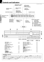
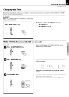
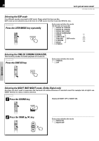
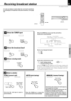
16 Controls and indicators INTRO SCAN indicator RANDOM indicator PARENTAL LOCK indicator PLAY/PAUSE indicator PROG. (Program) indicator TITLE indicator TRACK indicator CHAPTER indicator AUTO indicator TUNED indicator ST (Stereo) indicator CINEMA EQ mode indicator DVR-505/DVR-7000 (EN) B. BOOST indicator Preparations RDS indicator (only for U.K.) PBC indicator DVD indicator VCD indicator CD indicator MP3 indicator REPEAT indicators REPEAT A-B REPEAT Character information display section Display IN/OUT status indicator L : Left speaker C : Center speaker R : Right speaker LFE : Low Frequency Effect SW : Subwoofer LS : Left surround speaker S : Surround speakers RS : Right surround speaker ¡ ) ( * & ^ 1 2 1 STANDBY indicator 2 POWER switch LISTEN MODE indicators 3 DTS indicator 4 DOLBY DIGITAL indicator 5 PRO LOGIC indicator 6 DSP indicator 7 CS-5.1 indicator 8 BAND key 9 4, ¢ (Skip) keys 0 AV AUX S VIDEO jack 3 4 56 7 89 S VIDEO 0! ^ * o o o o o ¡ ¡ % ! AV AUX VIDEO jack @ AV AUX AUDIO jacks # AV AUX OPTICAL input jack $ PHONES jack % Door ^ 6 (PLAY/PAUSE) key & 7 (STOP) key * INPUT key ( VOLUME CONTROL knob ) 0 (EJECT) key ¡ Disc tray DIGITAL (OPTICAL) % @# $ STANDBY indicator The STANDBY indicator lights when the power cable is plugged into an outlet and the POWER switch is set to ON. When the POWER key on the remote control unit is pressed in STANDBY status, the STANDBY indicator goes out and the main unit reaches operation status. When the POWER switch is set to OFF in operation status, the unit will return to operation status when the POWER switch is set to ON again. When the POWER switch is set to OFF in STANDBY status, the unit will return to STANDBY status when the POWER switch is set to ON again.
-
 1
1 -
2
-
3
-
4
-
5
-
6
-
7
-
8
-
9
-
10
-
 11
11 -
 12
12 -
 13
13 -
 14
14 -
 15
15 -
 16
16 -
 17
17 -
 18
18 -
 19
19 -
 20
20 -
 21
21 -
22
-
23
-
24
-
25
-
26
-
27
-
28
-
29
-
30
-
31
-
32
-
33
-
34
-
35
-
36
-
37
-
38
-
39
-
40
-
41
-
42
-
43
-
44
-
45
-
46
-
47
-
48
-
49
-
50
-
51
-
52
-
53
-
54
-
55
-
56
-
57
-
58
-
59
-
60
-
61
-
62
-
63
-
64
-
65
-
66
-
67
-
68
 |
 |
