Kenwood TS-2000 Operation Manual - Page 104
Rtty Equipment, Hf Linear Amplifier, Antenna Tuner, Acc 2, Remote, Ant 1
 |
View all Kenwood TS-2000 manuals
Add to My Manuals
Save this manual to your list of manuals |
Page 104 highlights
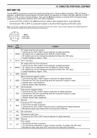
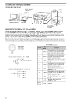
16 CONNECTING PERIPHERAL EQUIPMENT RTTY EQUIPMENT Use the ACC 2 connector to connect to the RTTY equipment. Connect the RTTY key output line to pin 2 of the ACC 2 connector. Connect the demodulation input line of the RTTY equipment to pin 3 of the ACC 2 connector {page 95}. Note: Do not share a single power supply between the transceiver and the RTTY equipment. Keep as wide a separation as possible between the transceiver and the RTTY equipment to reduce noise-pickup by the transceiver. MCP power supply Personal computer MCP TS-2000(X) ACC 2 HF LINEAR AMPLIFIER Connect an external transmit power amplifier to the REMOTE connector (1 male REMOTE connector (E07-0751-XX) is supplied). Switch ON the linear amplifier control relay via Menu No. 28A. The TX/RX relay response time is 10 ms when you have selected CW Full Break-in and 25 ms when you have selected CW Semi Break-in. Note: The TX/RX control method differs, depending on external amplifier models. Some amplifiers enter the TX mode when the control terminal is grounded. For those amplifiers, connect pin 2 of the REMOTE connector to the GND terminal of the amplifier and connect pin 4 of the connector to the control terminal of the amplifier. TS-2000(X)/ TS-B2000 Linear amplifier Control relay R T 2 4 5 1 3 6 7 GND AC LINE RF OUTPUT REMOTE Connector (Rear panel view) The TL-922 linear amplifier is a discontinued model. It may no longer be available in your area. REMOTE connector Pin No. Function 1 Speaker output 2 Common terminal 3 Standby; when grounded, the transceiver enters TX mode. 4 When connected with the common terminal, the amplifier enters TX mode. 5 When connected with the common terminal, the amplifier enters RX mode. 6 ALC input from amplifier 7 Approx. +12 V DC is output when in TX mode (10 mA max.). ANTENNA TUNER Use the ANT 1 and AT connectors to connect an external antenna tuner. If you connect the external tuner to the ANT 2 connector, the external tuner will not function. Note: While using an external antenna tuner with the TS-2000(X)/ TS-B2000, you cannot use the 6 m band to transmit. Connect your 6 m band antenna to the ANT 2 connector. External antenna tuner TS-2000(X)/TS-B2000 94 The AT-300 external antenna tuner is a discontinued model. It may no longer be available in your area.
-
 1
1 -
2
-
3
-
4
-
5
-
6
-
7
-
8
-
9
-
10
-
11
-
12
-
13
-
14
-
15
-
16
-
17
-
18
-
19
-
20
-
21
-
22
-
23
-
24
-
25
-
26
-
27
-
28
-
29
-
30
-
31
-
32
-
33
-
34
-
35
-
36
-
37
-
38
-
39
-
40
-
41
-
42
-
43
-
44
-
45
-
46
-
47
-
48
-
49
-
50
-
51
-
52
-
53
-
54
-
55
-
56
-
57
-
58
-
59
-
60
-
61
-
62
-
63
-
64
-
65
-
66
-
67
-
68
-
69
-
70
-
71
-
72
-
73
-
74
-
75
-
76
-
77
-
78
-
79
-
80
-
81
-
82
-
83
-
84
-
85
-
86
-
87
-
88
-
89
-
90
-
91
-
92
-
93
-
94
-
95
-
96
-
97
-
98
-
 99
99 -
 100
100 -
 101
101 -
 102
102 -
 103
103 -
 104
104 -
 105
105 -
 106
106 -
 107
107 -
 108
108 -
 109
109 -
110
-
111
-
112
-
113
-
114
-
115
-
116
-
117
-
118
-
119
-
120
-
121
-
122
-
123
-
124
-
125
-
126
-
127
-
128
-
129
-
130
-
131
-
132
-
133
-
134
-
135
-
136
-
137
-
138
-
139
-
140
-
141
-
142
-
143
-
144
-
145
-
146
-
147
-
148
-
149
-
150
-
151
-
152
-
153
-
154
-
155
-
156
 |
 |
