Kenwood TS-590S User Manual - Page 73
Connecting Peripheral Equipment
 |
View all Kenwood TS-590S manuals
Add to My Manuals
Save this manual to your list of manuals |
Page 73 highlights
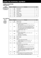
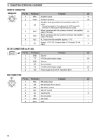
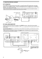
CONNECTING PERIPHERAL EQUIPMENT TERMINAL DESCRIPTIONS COM CONNECTOR Pin No. 1 2 3 4 5 6 7 8 9 Pin Name NC RXD TXD NC GND NC RTS CTS NC No connection Transmit data Receive data No connection Ground No connection Receive enable Transmit enable No connection Function ACC2 CONNECTOR Pin No. 1 2 3 4 5 6 7 8 9 10 11 12 13 Pin Name NC RTTY ANO GND PSQ NC NC GND PKS NC ANI GND SS Function No connection RTTY key input Audio output from the transceiver • Connect to the audio input of the TNC, MCP, or PC (or PC interface connection). • Audio output level is independent from the AF control setting. • Audio output level can be changed by adjusting the value in Menu No. 67. Set the value to a moderate audio output level. The default value of 4 is approximately 0.5 Vp-p, which is a standard modulating signal. The settings of 0 ~ 9 vary from approximately 0 Vp-p to 1.2 Vp-p. • Impedance: Approx. 10 kΩ. Ground Transceiver squelch control • Connect to the squelch input of the TNC, MCP, or PC connection interface. • Squelch open: Low impedance • Squelch closed: High impedance No connection No connection Ground PTT input for data communication • Connect to the PTT output of the TNC, MCP, or PC connection interface. • Microphone audio input mutes when transmitting. No connection Audio input for data communication • Connect to the audio output of the TNC, MCP, or PC (or PC interface connection). • Audio input level is independent from the microphone gain (set with the [MIC] key). • Audio input level can be changed by adjusting the value in Menu No. 66. The default value of 4 is approximately 10 mVrms, which is a standard modulating signal. The settings of 0 ~ 9 vary from approximately no modulation to approximately 1 mVrms. • Impedance: Approx. 10 kΩ. Ground PTT input (same as the front panel MIC connector) • During transmission, the audio input of ACC2 connector terminal 11 (ANI) and the USB terminal are muted. I/O - O I - - - I O - I/O - I O - O - - - I - I - I 65
-
 1
1 -
2
-
3
-
4
-
5
-
6
-
7
-
8
-
9
-
10
-
11
-
12
-
13
-
14
-
15
-
16
-
17
-
18
-
19
-
20
-
21
-
22
-
23
-
24
-
25
-
26
-
27
-
28
-
29
-
30
-
31
-
32
-
33
-
34
-
35
-
36
-
37
-
38
-
39
-
40
-
41
-
42
-
43
-
44
-
45
-
46
-
47
-
48
-
49
-
50
-
51
-
52
-
53
-
54
-
55
-
56
-
57
-
58
-
59
-
60
-
61
-
62
-
63
-
64
-
65
-
66
-
67
-
 68
68 -
 69
69 -
 70
70 -
 71
71 -
 72
72 -
 73
73 -
 74
74 -
 75
75 -
 76
76 -
 77
77 -
 78
78 -
79
-
80
-
81
-
82
-
83
-
84
-
85
-
86
-
87
-
88
-
89
-
90
-
91
-
92
 |
 |
