Kenwood TS-590S User Manual - Page 74
Connecting Peripheral Equipment, Remote Connector, Ext.at Connector For At-300, Mic Connector
 |
View all Kenwood TS-590S manuals
Add to My Manuals
Save this manual to your list of manuals |
Page 74 highlights
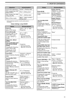
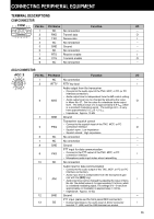
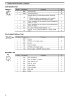
13 CONNECTING PERIPHERAL EQUIPMENT REMOTE CONNECTOR Pin No. Pin Name Function I/O 1 SPO Speaker output O 2 COM Common terminal I/O Standby; when grounded, the transceiver enters TX 3 SS mode. I • During transmission, the audio input of ACC2 connector terminal 11 (ANI) and the USB terminal are muted. 4 MKE When connected with the common terminal, the amplifier enters TX mode. I/O 5 BRK When connected with the common terminal, the amplifier enters RX mode. I/O 6 ALC ALC input from the amplifier (approx. -7 V). I 7 RL Approx. +12 V DC is output when in TX mode (10 mA max.). O EXT.AT CONNECTOR (for AT-300) Pin No. Pin Name Function I/O 1 GND Ground - 2 TT AT-300 control input/ output I/O 3 GND Ground - 4 NC No connection - 5 TS AT-300 control input/ output I/O 6 14S Power supply for EXT.AT Switched 13.8V. O MIC CONNECTOR Pin No. Pin Name Function I/O 1 MIC MIC signal input I 2 SS MIC standby (PTT) control I 3 MD MIC Down control I 4 MU MIC UP control I 5 8A Switched 8V O 6 NC No connection - 7 MSG MIC GND - 8 MCG GND - 66
-
 1
1 -
2
-
3
-
4
-
5
-
6
-
7
-
8
-
9
-
10
-
11
-
12
-
13
-
14
-
15
-
16
-
17
-
18
-
19
-
20
-
21
-
22
-
23
-
24
-
25
-
26
-
27
-
28
-
29
-
30
-
31
-
32
-
33
-
34
-
35
-
36
-
37
-
38
-
39
-
40
-
41
-
42
-
43
-
44
-
45
-
46
-
47
-
48
-
49
-
50
-
51
-
52
-
53
-
54
-
55
-
56
-
57
-
58
-
59
-
60
-
61
-
62
-
63
-
64
-
65
-
66
-
67
-
68
-
 69
69 -
 70
70 -
 71
71 -
 72
72 -
 73
73 -
 74
74 -
 75
75 -
 76
76 -
 77
77 -
 78
78 -
 79
79 -
80
-
81
-
82
-
83
-
84
-
85
-
86
-
87
-
88
-
89
-
90
-
91
-
92
 |
 |
