Kenwood TS-590S User Manual - Page 9
Installation
 |
View all Kenwood TS-590S manuals
Add to My Manuals
Save this manual to your list of manuals |
Page 9 highlights
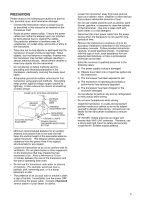
INSTALLATION ANTENNA CONNECTION An antenna system consists of an antenna, feed line, and ground. The transceiver can give excellent results if the antenna system and its installation are given careful attention. Use a properly adjusted 50 Ω antenna of good quality, a high-quality 50 Ω coaxial cable, and top-quality connectors. All connections must be clean and tight. After making the connections, match the impedance of the coaxial cable and antenna so that the SWR is 1.5:1 or less. High SWR will cause the transmit output to drop and may lead to radio frequency interference with consumer products such as stereo receivers and televisions. You may even cause interference with your own transceiver. Reports that your signal is distorted could indicate that your antenna system is not efficiently radiating your transceiver's power. Connect your primary HF/ 50 MHz antenna feed line to ANT 1 on the rear of the transceiver. If you are using two HF/ 50 MHz antennas, connect the secondary antenna to ANT 2. Refer to page 9 for the location of the antenna connectors. The LF band is outputed only from the DRV terminal. Note: ◆ Transmitting without connecting an antenna or other matched load may damage the transceiver. Always connect the antenna to the transceiver before transmitting. ◆ All fixed stations should be equipped with a lightning arrester to reduce the risk of fire, electric shock, and transceiver damage. ◆ The transceiver's protection circuit will activate when the SWR is greater than 1.5:1; however, do not rely on protection to compensate for a poorly functioning antenna system. GROUND CONNECTION At a minimum, a good DC ground is required to prevent such dangers as electric shock. For superior communications, a good RF ground is required against which the antenna system can operate. Both of these conditions can be met by providing a good earth ground for your station. Bury one or more ground rods or a large copper plate under the ground, then connect this to the transceiver GND terminal. Use heavy gauge wire or a copper strap, cut as short as possible, for this connection. Do not use a gas pipe, an electrical conduit, or a plastic water pipe as a ground. LIGHTNING PROTECTION Even in areas where lightning storms are less common, there is always a chance that a storm will occur each year. Consider carefully how to protect your equipment and home from lightning. The installation of a lightning arrestor is a start, but there is more that you can do. For example, terminate your antenna system transmission lines at an entry panel that you install outside your home. Ground this entry panel to a good outside ground, then connect the appropriate feed lines between the entry panel and your transceiver. When a lightning storm occurs, disconnecting the feed lines from your transceiver will ensure additional protection. DC POWER SUPPLY CONNECTION In order to use this transceiver, you need a separate 13.8 V DC power supply that must be purchased separately. Do not directly connect the transceiver to an AC outlet. Use the supplied DC power cable to connect the transceiver to a regulated power supply. Do not substitute a cable with smaller gauge wires. The current capacity of the power supply must be 20.5 A peak or more. First, connect the DC power cable to the regulated DC power supply; the red lead to the positive terminal and the black lead to the negative terminal. Next, connect the DC power cable to the transceiver's DC power connector. • Press the connectors firmly until the locking tab clicks. • Attach the line filter to the DC cable as shown below (E-type only). Note: ◆ Before connecting the DC power supply to the transceiver, be sure to switch OFF the DC power supply and transceiver. ◆ Do not plug the DC power supply into an AC outlet until you make all connections. E-type only Fuse (25 A) TS-590S Black (−) DC Power supply (20.5 A or more) Red (+) 1
-
 1
1 -
2
-
3
-
 4
4 -
 5
5 -
 6
6 -
 7
7 -
 8
8 -
 9
9 -
 10
10 -
 11
11 -
 12
12 -
 13
13 -
 14
14 -
15
-
16
-
17
-
18
-
19
-
20
-
21
-
22
-
23
-
24
-
25
-
26
-
27
-
28
-
29
-
30
-
31
-
32
-
33
-
34
-
35
-
36
-
37
-
38
-
39
-
40
-
41
-
42
-
43
-
44
-
45
-
46
-
47
-
48
-
49
-
50
-
51
-
52
-
53
-
54
-
55
-
56
-
57
-
58
-
59
-
60
-
61
-
62
-
63
-
64
-
65
-
66
-
67
-
68
-
69
-
70
-
71
-
72
-
73
-
74
-
75
-
76
-
77
-
78
-
79
-
80
-
81
-
82
-
83
-
84
-
85
-
86
-
87
-
88
-
89
-
90
-
91
-
92
 |
 |
