KitchenAid KDTF924PPS Owners Manual - Page 21
Wiring configuration, Home Wire or
 |
View all KitchenAid KDTF924PPS manuals
Add to My Manuals
Save this manual to your list of manuals |
Page 21 highlights
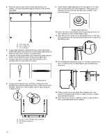
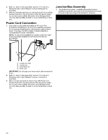
6. Attach one cable fitting to the junction box cable from the dishwasher paying thorough attention to the orientation (see below figure). The cable fitting shall tighten against the secondary insulation (PVC jacket). A A. 0.25" (6.35 mm) minimum 10. Route wire ends into the junction box through the round holes on the sides. Securely attach the cable fittings to the junction box using plastic mounting nuts supplied with the cable fittings. Hand tighten the mounting nuts to the cable fittings and then use a crescent wrench to tighten another 1/4 turn. Use a second wrench or pliers to secure the cable fitting body when tightening the mounting nut. Use wrench and/or pliers to fully tighten the elongated (strain relief) nut against the strain relief body. 7. For Direct (home) wire connection (12-2/14-2 non-metallic sheathed/Romex), Strip jacket insulation of the home wire to expose the wires to the length of 51/16" (129.3 mm) as shown below. Strip each wire end by 0.75" (19 mm). Attach the second cable fitting to home wiring paying attention to the orientation (see below figure). Use wrench and/or pliers to fully tighten the elongated (strain relief) nut against the strain relief body. A B 11. Connect wires together inside the junction box using the supplied wire nuts. Connect wires of the same color together (black to black, white to white, and bare/green to green). NOTE: Do not pre-twist wires before making connections. Wiring configuration Home Wire or Power Cord white black bare/green Junction Box Cable white black green C A. 33/4" (95 mm) B. 0.75" (19 mm) C. 0.25" (6.35 mm) minimum 8. For Direct (home) wire connection using armored cable or flexible metal conduit use only a UL/CSA-approved metallic strain relief for the type of conduit being used. Ensure 4" (101.6 mm) of wire is extending out past the end of the strain relief. Strip each wire end by 0.75" (19 mm). Attach the strain relief to the home wiring per the strain relief manufacturer's instructions. Attach strain relief to the box per the strain relief manufacturer's installation instructions. 9. For power cord connection, attach the second cable fitting to the power cord paying attention to the orientation (see below figure). Use wrench and/or pliers to fully tighten the elongated (strain relief) nut against the strain relief body. 12. To apply a wire nut, hold the stripped/bare ends of wires parallel to each other with their ends aligned. Firmly push wires into a wire nut and twist clockwise until secure (the insulated wires outside the connector begin to twist). Gently tug on each wire making sure they are secure. A A. 0.25" (6.35 mm) minimum NOTE: Non-metallic sheathed wire is for direct wire connection only. 21
-
 1
1 -
2
-
3
-
4
-
5
-
6
-
7
-
8
-
9
-
10
-
11
-
12
-
13
-
14
-
15
-
 16
16 -
 17
17 -
 18
18 -
 19
19 -
 20
20 -
 21
21 -
 22
22 -
 23
23 -
 24
24 -
 25
25 -
 26
26 -
27
-
28
-
29
-
30
-
31
-
32
-
33
-
34
-
35
-
36
-
37
-
38
-
39
-
40
-
41
-
42
-
43
-
44
-
45
-
46
-
47
-
48
-
49
-
50
-
51
-
52
-
53
-
54
-
55
-
56
-
57
-
58
-
59
-
60
-
61
-
62
-
63
-
64
 |
 |
