LG LSC27914ST Owner's Manual - Page 36
Temperature sensing circuit, 6. Switch entry circuit
 |
View all LG LSC27914ST manuals
Add to My Manuals
Save this manual to your list of manuals |
Page 36 highlights
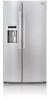
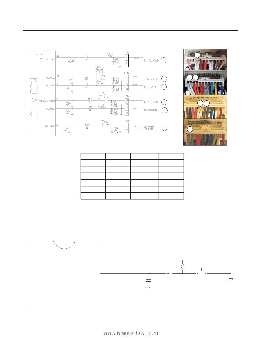
1-5. Temperature sensing circuit A A B BC C D DE E F F ITEM A B C D E F SENSOR RT F D R1 R2 I/M LOCATION CON5 PIN4,5 CON6 PIN1,2 CON6 PIN3,4 CON7 PIN5,6 CON7 PIN7,8 CON8 PIN1,2 COLOR 2*WH 2*WH 2*BO 2*WH 2*GY 2*GY 1-6. Switch entry circuit The following circuits are sensing signal form the test switch, damper motor reed switch for testing and diagnosing the refrigerator. IC1 P67 63 MICOM CC10* 104 R84* 2K R28* 4.7K SW1 - 35 -
-
 1
1 -
2
-
3
-
4
-
5
-
6
-
7
-
8
-
9
-
10
-
11
-
12
-
13
-
14
-
15
-
16
-
17
-
18
-
19
-
20
-
21
-
22
-
23
-
24
-
25
-
26
-
27
-
28
-
29
-
30
-
 31
31 -
 32
32 -
 33
33 -
 34
34 -
 35
35 -
 36
36 -
 37
37 -
 38
38 -
 39
39 -
 40
40 -
 41
41 -
42
-
43
-
44
-
45
-
46
-
47
-
48
-
49
-
50
-
51
-
52
-
53
-
54
-
55
-
56
-
57
-
58
-
59
-
60
-
61
-
62
-
63
-
64
-
65
-
66
-
67
-
68
-
69
-
70
-
71
-
72
-
73
-
74
-
75
-
76
-
77
-
78
-
79
-
80
-
81
-
82
-
83
-
84
-
85
-
86
-
87
-
88
-
89
-
90
-
91
-
92
-
93
-
94
-
95
-
96
-
97
-
98
-
99
-
100
-
101
-
102
-
103
-
104
-
105
-
106
-
107
-
108
-
109
-
110
-
111
-
112
-
113
-
114
-
115
-
116
-
117
-
118
-
119
-
120
-
121
-
122
-
123
-
124
-
125
-
126
-
127
-
128
-
129
-
130
-
131
-
132
-
133
-
134
-
135
-
136
-
137
-
138
-
139
-
140
 |
 |
1-5. Temperature sensing circuit
SW1
R28*
IC1
MICOM
CC10*
104
4.7K
63
2K
R84*
P67
I/M
2*GY
CON8 PIN1,2
R2
F
2*WH
CON7 PIN7,8
R1
E
2*BO
CON7 PIN5,6
D
D
2*WH
CON6 PIN3,4
F
C
CON6 PIN1,2
B
2*WH
CON5 PIN4,5
RT
A
COLOR
LOCATION
SENSOR
ITEM
I/M
R2
F
R1
E
D
D
F
C
B
RT
A
A
B
C
D
E
F
2*GY
1-6. Switch entry circuit
The following circuits are sensing signal form the test switch, damper motor reed switch for testing and diagnosing the
refrigerator.
- 35 -
A
B
C
D
E
F