LG LSC27914ST Owner's Manual - Page 51
Ic1 Micom
 |
View all LG LSC27914ST manuals
Add to My Manuals
Save this manual to your list of manuals |
Page 51 highlights
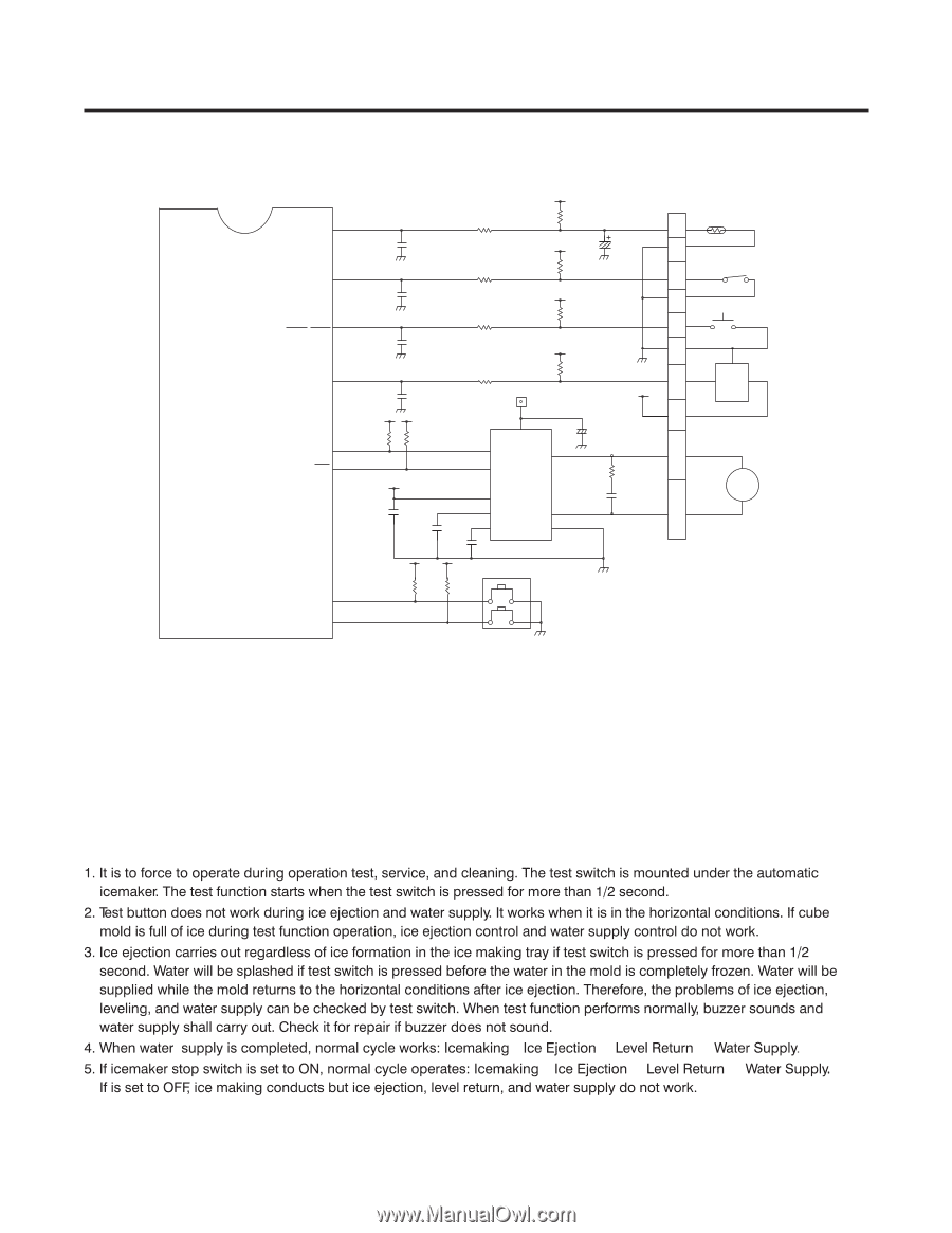
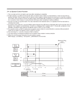
4. ICEMAKER CIRCUIT IC1 MICOM P62_AIN02 22 P00_INT0_A3 10 9 P20_INT5_STOP 44 P10_TC1 P22_XTOUT 7 P12_PPG 46 CC23* 223 CC24* 223 CC25* 223 R58* 2K R60 2K R62 2K R63 CC26* 2K 223 78 R65* 4.7K R66* 4.7K Forward 5 Reverse 6 CC27* 223 4 3 CC28* 9 223 CC29* 223 IC11 BA6222 RIM1* 16.2KF R59 2K CE14 10uF /50V R61 4.7K R64* 2K CON8 1 2 ICE MAKER SENSOR 3 ICE MAKER 4 STOP S/W 5 ICE MAKER 6 TEST S/W 2 7 3 HALL 1 IC + CE15 8 100uF /25V 10 9 R67 68,1/2W CM4 2 1 223/100V 10 M ICE MAKER MOTOR P67_AIN07_STOP3 27 P70_AIN8 28 R25* R24* 4.7K 4.7K SW 2 2 1 The above icemaker circuits are applied to LSC27914** and composed of icemaker unit in the freezer and icemaker driving part of main PWB. Water is supplied to the icemaker cube mold through the solenoid relay for ice valve of solenoid valve in the mechanical area by opening valve for the same time. Water supply automatically stops when water supply time is elapsed. This circuit is to realize the functions such as ice ejection of icemaker cube mold, ice full detection, leveling, ice making test switch input detection is the same as the door switch input detection circuit of main PWB. ª ª ª ª ª ª - 50 -
-
 1
1 -
2
-
3
-
4
-
5
-
6
-
7
-
8
-
9
-
10
-
11
-
12
-
13
-
14
-
15
-
16
-
17
-
18
-
19
-
20
-
21
-
22
-
23
-
24
-
25
-
26
-
27
-
28
-
29
-
30
-
31
-
32
-
33
-
34
-
35
-
36
-
37
-
38
-
39
-
40
-
41
-
42
-
43
-
44
-
45
-
 46
46 -
 47
47 -
 48
48 -
 49
49 -
 50
50 -
 51
51 -
 52
52 -
 53
53 -
 54
54 -
 55
55 -
 56
56 -
57
-
58
-
59
-
60
-
61
-
62
-
63
-
64
-
65
-
66
-
67
-
68
-
69
-
70
-
71
-
72
-
73
-
74
-
75
-
76
-
77
-
78
-
79
-
80
-
81
-
82
-
83
-
84
-
85
-
86
-
87
-
88
-
89
-
90
-
91
-
92
-
93
-
94
-
95
-
96
-
97
-
98
-
99
-
100
-
101
-
102
-
103
-
104
-
105
-
106
-
107
-
108
-
109
-
110
-
111
-
112
-
113
-
114
-
115
-
116
-
117
-
118
-
119
-
120
-
121
-
122
-
123
-
124
-
125
-
126
-
127
-
128
-
129
-
130
-
131
-
132
-
133
-
134
-
135
-
136
-
137
-
138
-
139
-
140
 |
 |