Lantronix XPort APS: Modbus Protocol User Guide - Page 13
Modem Control Settings - direct
 |
View all Lantronix XPort manuals
Add to My Manuals
Save this manual to your list of manuals |
Page 13 highlights
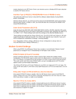
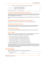
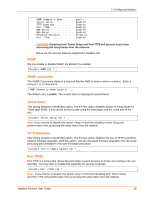
3: Configuring Modbus master attached to one IAP Device Server can remotely access a Modbus/ASCII slave attached to another IAP Device Server. Interface Type (1=RS232 2=RS422/RS485+4-wire 3=RS485+2-wire) This allows the IAP Device Server to deal with the software-related details of using RS232, RS422, and RS485. With the XPress DR-IAP, you still must set the external red RS232/RS485 switch appropriately. With the UDS-10-IAP or CoBox-FL-IAP, you must still select the correct pins for RS232 or the shared RS422/485 pins. Enter Serial Parameters (B,D,P,S) Enter the baud rate (300/ 600/ 1200/ 2400/ 4800/ 9600/ 19,200 or 38,400), data bits (7/8), parity (N/O/E), and stop bits (1/2) in the classic "DOS Mode Command" style. Examples are 9600, 8, E, 1 or 1200, 7, O, 2. These settings must match the settings on the attached Modbus device. These settings are valid with the XPress DR-IAP only. The UDS-10-IAP and CoBox-FL IAP also support baud rates 57,600 and 115,200. The UDS-10-IAP supports only 1 stop bit. If you try to set an unsupported combination of settings, a warning displays. Note: Regardless of these settings, IAP Device Server configuration is always done on CH1 with RS232 and a setting of 9600,8,N, 1. Modem Control Settings When using RS232, the IAP Device Server has a number of user-definable "Modem Control" parameters to manage RTS/CTS handshaking for half-duplex radio modems. RTS/CTS Mode (1=Fixed 2=Variable) Answer 1 and the IAP Device Server output is fixed to high. Answer 2 to enable modem handshaking. The RTS/CTS output is active when the device server is transmitting on the serial port. This setting is very different from the hardware or RTS/CTS flow-control used with printers. This mode cannot work with a direct RS232 cable, as each end only asserts its RTS control signal to power up intermediate transmitters. The XPress DR-IAP has a DTE-style RS232 port, so RTS is an output and CTS is an input. The UDS-10-IAP and CoBox-FL-IAP have a DCE-style RS232 port, so RTS is an input and CTS is an output. Delay after Output of RTS (0-1275 ms, 5ms increments) Only asked if RTS/CTS mode is variable. After the IAP Device Server asserts the RTS/CTS signal, it delays from 0 to 1275 ms before continuing. Normally this is set to 0. Only set a value here if your device, modem, or cable is non-standard. Wait for CTS to Go Active (N/Y) Only asked if RTS/CTS mode is variable. Answering N causes the IAP Device Server to ignore the RTS/CTS response from the modem. Answering Y causes the IAP Device Server to wait for the RTS/CTS response from the modem. Do not answer Y unless you know that the cable is wired properly to support this signal. Modbus Protocol User Guide 13
-
 1
1 -
2
-
3
-
4
-
5
-
6
-
7
-
 8
8 -
 9
9 -
 10
10 -
 11
11 -
 12
12 -
 13
13 -
 14
14 -
 15
15 -
 16
16 -
 17
17 -
 18
18 -
19
-
20
-
21
-
22
-
23
-
24
-
25
-
26
-
27
-
28
-
29
-
30
-
31
-
32
-
33
 |
 |
