Lantronix XPort APS: Modbus Protocol User Guide - Page 24
XPort Implementation
 |
View all Lantronix XPort manuals
Add to My Manuals
Save this manual to your list of manuals |
Page 24 highlights
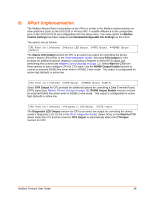
6: XPort Implementation The Modbus Master/Slave functionality on the XPort is similar to the Modbus implementation on other platforms (such as the UDS1100 or XPress-DR). A notable difference is the configurable pins on the XPort (CP1-3) are configurable from the setup menu. The menu option for Modem Control Settings has been replaced with Modem/Configurable Pin Settings on the XPort. The options are as follows: CP1 Function (1=Unused, 2=Status LED Output, 3=RTS Output, 4=RS485 Output Enable) The Status LED Output function for CP1 is an active low output for controlling the device server's Status LED (LED1 in the XPort Integration Guide). Selecting RTS Output for CP1 prompts for additional options related to controlling a Request to Send (RTS) signal and performing flow control (see Modem Control Settings on page 13). Select Wait for CTS from these options to auto-configure CP3 for CTS Input. Use the RS485 Output Enable function to control an external RS485 line driver when in RS485 2-wire mode. This output is configurable for active high (default) or active low. CP2 Function (1=Unused, 2=DTR Output, 3=RS485 Output Enable) Select DTR Output for CP2 prompts for additional options for controlling a Data Terminal Ready (DTR) signal (see Modem Control Settings on page 13). RS485 Output Enable function controls an external RS485 line driver when in RS485 2-wire mode. This output is configurable for active high (default) or active low. CP3 Function (1=Unused, 2=Diagnostic LED Output, 3=CTS Input) The Diagnostic LED Output function for CP3 is an active low output for controlling the device server's Diagnostic LED (LED3 in the XPort Integration Guide). Select (Y)es on the Wait for CTS option under the CP1 function menu for RTS Output to automatically select the CTS Input function for CP3. Modbus Protocol User Guide 24
-
 1
1 -
2
-
3
-
4
-
5
-
6
-
7
-
8
-
9
-
10
-
11
-
12
-
13
-
14
-
15
-
16
-
17
-
18
-
 19
19 -
 20
20 -
 21
21 -
 22
22 -
 23
23 -
 24
24 -
 25
25 -
 26
26 -
 27
27 -
 28
28 -
 29
29 -
30
-
31
-
32
-
33
 |
 |
