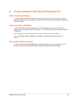
Lantronix XPort APS: Modbus Protocol User Guide - Page 26
xPico Implementation, Modbus Protocol User Guide
 |
View all Lantronix XPort manuals
Add to My Manuals
Save this manual to your list of manuals |
Page 26 highlights
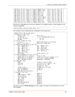
7: xPico Implementation CP1 Function (hit space to toggle) GPIO (In) Invert (active low) (Y) ? A function should be assigned to each configurable pin. GPIO (Input) should be the default for all unused or unassigned pins. CP1 Function (hit space to toggle) GPIO (In) (Y) ? CP2 Function (hit space to toggle) GPIO (Out) (N) ? CP3 Function (hit space to toggle) DCD (IN) Channel-1 (N) ? CP4 Function (hit space to toggle) DTR (Out) Channel-1 (Y) ? CP5 Function (hit space to toggle) Channel-1 Status LED (Y) ? CP6 Function (hit space to toggle) Channel-2 Status LED (Y) ? CP7 Function (hit space to toggle) RS485 Select (Y) ? CP8 Function (hit space to toggle) RS485 2 Wire Select (Y) ? Invert (active low) Invert (active low) Invert (active low) Invert (active low) Invert (active low) Invert (active low) Invert (active low) Invert (active low) After all the configurable pins have been assigned, the standard modem control settings can be entered if applicable. DTR Mode (1=Fixed 2=Variable) (1) ? RTS/CTS Mode (1=Fixed 2=Variable) (1) ? The setting for each configurable pin is displayed in the setup menu. Modbus/TCP to RTU Bridge Setup 1) Network/IP Settings: IP Address 0.0.0.0/DHCP/BOOTP/AutoIP Default Gateway not set --- Netmask not set --- 2) Serial & Mode Settings: Protocol Modbus/RTU,Slave(s) attached Serial Interface 9600,8,N,1,RS232,CH1 3) Modem/Configurable Pin Settings: CP1..!GPIO (In) CP2.. GPIO (Out) CP3.. DCD (IN) Channel-1 CP4..!DTR (Out) Channel-1 CP5..!Channel-1 Status LED CP6..!Channel-2 Status LED CP7..!RS485 Select CP8..!RS485 2 Wire Select DTR Output Fixed High/Active RTS Output Fixed High/Active 4) Advanced Modbus Protocol settings: Slave Addr/Unit Id Source .. Modbus/TCP header Modbus Serial Broadcasts ... Disabled (Id=0 auto-mapped to 1) MB/TCP Exception Codes ..... Yes (return 00AH and 00BH) Char, Message Timeout ...... 00050msec, 05000msec 7) Security Settings: SNMP Enabled SNMP Community Name ........ public Telnet Setup Enabled TFTP Download Enabled Port 77FEh Enabled Web Server Enabled Enhanced Password .......... Disabled Port 77F0h Enabled D)efault settings, S)ave, Q)uit without save Select Command or parameter set (1..7) to change: Modbus Protocol User Guide 26
-
 1
1 -
2
-
3
-
4
-
5
-
6
-
7
-
8
-
9
-
10
-
11
-
12
-
13
-
14
-
15
-
16
-
17
-
18
-
19
-
20
-
 21
21 -
 22
22 -
 23
23 -
 24
24 -
 25
25 -
 26
26 -
 27
27 -
 28
28 -
 29
29 -
 30
30 -
 31
31 -
32
-
33
 |
 |
