Lantronix XPort APS: Modbus Protocol User Guide - Page 25
xPico Implementation
 |
View all Lantronix XPort manuals
Add to My Manuals
Save this manual to your list of manuals |
Page 25 highlights
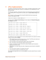
7: xPico Implementation The Modbus master/slave functionality of xPico is similar to the Modbus implementation on other platforms such as the UDS1100 or XPress-DR. The difference is the configurable pins on the xPico (CP1-CP8) . The xPico has 2 serial ports. Choose the serial port, hence the firmware uses for sending and receiving Modbus/RTU or Modbus/ASCII serial data under the Serial & Mode Settings menu option. Note: Channel 1 on xPico supports RS-232 and RS-422/RS-485 2/4-wire modes while Channel 2 only supports RS-232. Use serial connector (1=CH1 2=CH2) (1) ? The menu option for Modem Control Settings has been replaced with Modem/Configurable Pin Settings on the xPico. CP1 Function (hit space to toggle) GPIO (In) CP2 Function (hit space to toggle) GPIO (Out) CP3 Function (hit space to toggle) DCD (IN) Channel-1 CP4 Function (hit space to toggle) DTR (Out) Channel-1 CP5 Function (hit space to toggle) Channel-1 Status LED CP6 Function (hit space to toggle) Channel-2 Status LED CP7 Function (hit space to toggle) RS485 Select CP8 Function (hit space to toggle) RS485 2 Wire Select The assignment for each configurable pin is set by cycling through the menu options by entering a space or any key other than Enter. GPIO assigns the pin as a general purpose input or output. The GPIOs can be written and read via Modbus/TCP when in slave attached mode. DTR is the Modem Control Output (MCO) signal for Data Terminal Ready. DCD is the Modem Control input (MCI) signal for Data set Ready. Channel 1 and Channel 2 status LED show the activity of Modbus packet transactions happening in the device server. RS485 Select is an output made active when configuring the serial channel for RS422/485 operation. RTS is the out pin for channel 2 for hardware flow control. CTS is the input for channel 2 for hardware flow control. After assigning the applicable function by pressing Enter, you are then asked if the pin is inverted (active low). Modbus Protocol User Guide 25
-
 1
1 -
2
-
3
-
4
-
5
-
6
-
7
-
8
-
9
-
10
-
11
-
12
-
13
-
14
-
15
-
16
-
17
-
18
-
19
-
 20
20 -
 21
21 -
 22
22 -
 23
23 -
 24
24 -
 25
25 -
 26
26 -
 27
27 -
 28
28 -
 29
29 -
 30
30 -
31
-
32
-
33
 |
 |
