Lenovo NetVista IBM PC300 (Type 2169) - Hardware Maintenance Manual (September - Page 126
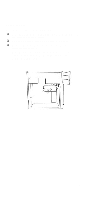
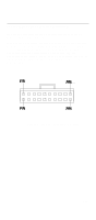
Layout of system board of the machine type 2169, Slot for a TV-Out/LCD Panel Riser
 |
View all Lenovo NetVista manuals
Add to My Manuals
Save this manual to your list of manuals |
Page 126 highlights
Layout of system board of the machine type 2169 ATX1 JP2 CPUFAN1 DIMM1 DIMM2 Socket-370 COM2 SIR1 JP3 CASFAN1 FDD1 IDE2 IDE1 CD1 CD2 LED1 MODEM2 FP1 TV-Out/LCD Panel Riser Slot PCI1 PCI2 JP1 J1 PANEL1 WOM1 LED2 J2 WOL1 USB1 Component Socket-370 PCI 1, 2 TV-Out/LCD Panel Riser DIMM 1, 2 FDD1 IDE1, IDE2 ATX1 SIR1 PANEL1 WOM1 WOL1 USB1 *LED1 **LED2 COM2 CASFAN1 CPUFAN1 MODEM2 Description Socket for PPGA Celeron Processor Two 32-bit PCI Slots Slot for a TV-Out/LCD Panel Riser card. Two slots for 168-pin SDRAM memory module Connector for floppy disk drives Primary and secondary IDE channels Connector for ATX power supply Connector for optional infrared port Panel connector for switches and indicators Connector for modem wake up Connector for LAN wake up Connector for auxiliary USB ports 3VSB LED for SDRAM Power LED Connector for serial port 2/4 Power connector for case cooling fan Power connector for CPU cooling fan Connector for modem DAA module CD1 Audio connector for CD-ROM/DVD drive 124
-
 1
1 -
2
-
3
-
4
-
5
-
6
-
7
-
8
-
9
-
10
-
11
-
12
-
13
-
14
-
15
-
16
-
17
-
18
-
19
-
20
-
21
-
22
-
23
-
24
-
25
-
26
-
27
-
28
-
29
-
30
-
31
-
32
-
33
-
34
-
35
-
36
-
37
-
38
-
39
-
40
-
41
-
42
-
43
-
44
-
45
-
46
-
47
-
48
-
49
-
50
-
51
-
52
-
53
-
54
-
55
-
56
-
57
-
58
-
59
-
60
-
61
-
62
-
63
-
64
-
65
-
66
-
67
-
68
-
69
-
70
-
71
-
72
-
73
-
74
-
75
-
76
-
77
-
78
-
79
-
80
-
81
-
82
-
83
-
84
-
85
-
86
-
87
-
88
-
89
-
90
-
91
-
92
-
93
-
94
-
95
-
96
-
97
-
98
-
99
-
100
-
101
-
102
-
103
-
104
-
105
-
106
-
107
-
108
-
109
-
110
-
111
-
112
-
113
-
114
-
115
-
116
-
117
-
118
-
119
-
120
-
 121
121 -
 122
122 -
 123
123 -
 124
124 -
 125
125 -
 126
126 -
 127
127 -
 128
128 -
 129
129 -
 130
130 -
 131
131 -
132
-
133
-
134
-
135
-
136
-
137
-
138
-
139
-
140
-
141
-
142
-
143
-
144
-
145
-
146
-
147
-
148
-
149
-
150
-
151
-
152
-
153
-
154
-
155
-
156
-
157
 |
 |
