Lenovo PC 300PL Technical Information Manual 6275, 6285 - Page 47
The number of data locations included
 |
View all Lenovo PC 300PL manuals
Add to My Manuals
Save this manual to your list of manuals |
Page 47 highlights
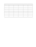
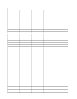
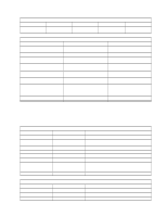
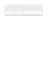
Chapter 6. IBM System Management Tools Figure 22 (Page 2 of 2). Device Types Device Type Device Number 1F 7 Device Number Owner data Dynamic Update No Comment User specified information Figure 23. Serialization Information Area Header Offset (Hex) Contents 00-03 SER# 4 Length 5 maxFields 6 versionID 7 HdrShchecksum 8 AreaCheckSum 9 AreaStatus 0A-0F reserved Description Area Identifier = SER# for serialization area Number and bytes in each entry field Maximum number of entities that may reside in the area Serialization Information Area version identifier Checksum for the serialization data area Checksum for the serialization data area Provides status about the area as follows: bit 0: RF dirty - a value of 1 indicates The data in the area has been modified by an RF operation. Reserved for future use The two checksums for the serialization area are included in the area header. The checksum for the header is used to check the data contained in the first 7 bytes (0-6) of the header. The checksum for the area is used to check the data located in all of the area locations. The number of data locations included in the checksum can be found from the Length and maxFields fields of the header as Length * maxFields + 16. Figure 24. User Information Area Header Offset (Hex) Contents 00-03 USR# 4 Length 5 Reserved 6 versionID 7 HdrChecksum 8 AreaChecksum 9 AreaStatus 0A-0F Reserved Description Area Identifier = USR# Number of bytes used in User Information Area including header Reserved for future use. Must read 0. Asset Information Area version identifier Checksum for the first 7 bytes of the header Checksum for all user data Provides status about the area as follows: bit 0: RF dirty - a value of 1 indicates that data in the area has been modified by an RF operation. Reserved for future use Figure 25 (Page 1 of 2). Configuration Information Area Header Byte Offset (Hex) Contents Description 00-03 CON# Area Identifier = CON# for configuration area 4 Length Number of bytes used in configuration area including header 5 Reserved Reserved for future use Chapter 6. IBM System Management Tools 35
-
 1
1 -
2
-
3
-
4
-
5
-
6
-
7
-
8
-
9
-
10
-
11
-
12
-
13
-
14
-
15
-
16
-
17
-
18
-
19
-
20
-
21
-
22
-
23
-
24
-
25
-
26
-
27
-
28
-
29
-
30
-
31
-
32
-
33
-
34
-
35
-
36
-
37
-
38
-
39
-
40
-
41
-
 42
42 -
 43
43 -
 44
44 -
 45
45 -
 46
46 -
 47
47 -
 48
48 -
 49
49 -
 50
50 -
 51
51 -
 52
52 -
53
-
54
-
55
-
56
-
57
-
58
-
59
-
60
-
61
-
62
-
63
-
64
-
65
-
66
-
67
-
68
-
69
-
70
-
71
-
72
-
73
-
74
-
75
-
76
-
77
-
78
-
79
-
80
-
81
-
82
-
83
-
84
-
85
-
86
-
87
-
88
 |
 |
