Lenovo RS110 User Guide - Page 29
System-board, switches, jumpers
 |
UPC - 884343312484
View all Lenovo RS110 manuals
Add to My Manuals
Save this manual to your list of manuals |
Page 29 highlights
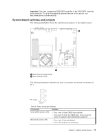
Important: Use only a supported SAS/SATA controller in the SAS/SATA controller card connector. For a list of supported optional devices for the server, see http://www.lenovo.com/thinkserver. System-board switches and jumpers The following illustration shows the switches and jumpers on the system board. 1 Boot block recovery jumper 2 Clear CMOS jumper The following illustration identifies the pins on a jumper and shows the location of pin 1. 3 2 Pin 1 mark 1 Table 2. Switch and jumper settings Component Settings Clear CMOS jumper (JP3) v Pins 1 and 2: Keep CMOS data (default) v Pins 2 and 3: Clear the CMOS data, which clears the power-on password and administrator password Boot block jumper (JP4) v Pins 1 and 2: Normal (default) v Pins 2 and 3: Boot from boot block Chapter 2. Installing optional devices 15
-
 1
1 -
2
-
3
-
4
-
5
-
6
-
7
-
8
-
9
-
10
-
11
-
12
-
13
-
14
-
15
-
16
-
17
-
18
-
19
-
20
-
21
-
22
-
23
-
 24
24 -
 25
25 -
 26
26 -
 27
27 -
 28
28 -
 29
29 -
 30
30 -
 31
31 -
 32
32 -
 33
33 -
 34
34 -
35
-
36
-
37
-
38
-
39
-
40
-
41
-
42
-
43
-
44
-
45
-
46
-
47
-
48
-
49
-
50
-
51
-
52
-
53
-
54
-
55
-
56
-
57
-
58
-
59
-
60
-
61
-
62
-
63
-
64
-
65
-
66
-
67
-
68
-
69
-
70
-
71
-
72
-
73
-
74
-
75
-
76
 |
 |
