Lenovo RS110 User Guide - Page 31
System-board
 |
UPC - 884343312484
View all Lenovo RS110 manuals
Add to My Manuals
Save this manual to your list of manuals |
Page 31 highlights
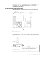
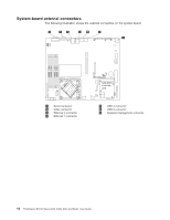
System-board LEDs The following illustration shows the light-emitting diodes (LEDs) on the system board. 1 PCI Express slot 2 error LED 2 PCI Express slot 1 error LED 3 SAS/SATA controller error LED 4 Baseboard management controller heartbeat LED 5 Power good LED 6 Standby power LED 7 Voltage regulator error LED 8 Fan 5 error LED 9 Fan 4 error LED 10 Fan 1 error LED 11 Fan 2 error LED 12 Fan 3 error LED 13 DIMM 1 error LED 14 DIMM 2 error LED 15 DIMM 3 error LED 16 DIMM 4 error LED Table 3. System-board LEDs LED Description Error LEDs When one of these LEDs is lit, it indicates that the associated component has failed. Baseboard management controller heartbeat LED This LED flashes to indicate that the mini-BMC is functioning normally. Standby power LED When this LED is lit, it indicates that the server is connected to ac power. Chapter 2. Installing optional devices 17
-
 1
1 -
2
-
3
-
4
-
5
-
6
-
7
-
8
-
9
-
10
-
11
-
12
-
13
-
14
-
15
-
16
-
17
-
18
-
19
-
20
-
21
-
22
-
23
-
24
-
25
-
 26
26 -
 27
27 -
 28
28 -
 29
29 -
 30
30 -
 31
31 -
 32
32 -
 33
33 -
 34
34 -
 35
35 -
 36
36 -
37
-
38
-
39
-
40
-
41
-
42
-
43
-
44
-
45
-
46
-
47
-
48
-
49
-
50
-
51
-
52
-
53
-
54
-
55
-
56
-
57
-
58
-
59
-
60
-
61
-
62
-
63
-
64
-
65
-
66
-
67
-
68
-
69
-
70
-
71
-
72
-
73
-
74
-
75
-
76
 |
 |
