Lenovo ThinkCentre A58 User Manual - Page 109
Replacing the system board, wait three to five minutes to let the computer cool before removing
 |
View all Lenovo ThinkCentre A58 manuals
Add to My Manuals
Save this manual to your list of manuals |
Page 109 highlights
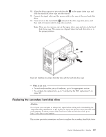
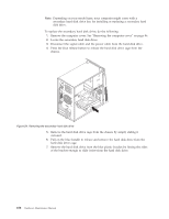
What to do next: v To work with another piece of hardware, go to the appropriate section. v To complete the replacement, go to "Completing the FRU replacement" on page 120. Replacing the system board Attention Do not open your computer or attempt any repair before reading and understanding the "Important safety information" in the ThinkCentre Safety and Warranty Guide that came with your computer. To obtain a copy of the ThinkCentre Safety and Warranty Guide, go to: http://www.lenovo.com/support This section provides instructions on how to replace the system board. CAUTION: The heat sink and microprocessor might be very hot. Turn off the computer and wait three to five minutes to let the computer cool before removing the computer cover. Note: When replacing the system board, you must order a new retention module for the new system board. Make sure you have a retention module for the new system board before continuing this procedure. To replace the system board, do the following: 1. Remove the computer cover. See "Removing the computer cover" on page 86. 2. Remove the primary hard disk drive with the hard disk drive cage. See "Replacing the primary hard disk drive" on page 105. 3. Lay the computer on its side to make the system board more accessible. 4. Remove all memory modules and adapter cards that are currently installed. See "Installing or replacing a memory module" on page 90 and "Installing or replacing a PCI card" on page 92. 5. Carefully take note of the location of all cable connectors on the system board and disconnect all the cables. See "Locating parts on the system board" on page 89. 6. Remove the heat sink and fan assembly from the failing system board. See "Replacing the heat sink and fan assembly" on page 98. 7. Remove the screws that secure the system board to the chassis. 8. Carefully move the system board out of the chassis. 9. Remove the microprocessor socket cover from the new system board. 10. Remove the microprocessor from the failing system board and install it on the new system board. See "Replacing the microprocessor" on page 100. 11. The failing system board must be returned with a microprocessor socket cover to protect the pins during shipping and handling. Install the microprocessor socket cover removed from the new system board on the failing system board. Chapter 8. Replacing FRUs - Tamdhu 103
-
 1
1 -
2
-
3
-
4
-
5
-
6
-
7
-
8
-
9
-
10
-
11
-
12
-
13
-
14
-
15
-
16
-
17
-
18
-
19
-
20
-
21
-
22
-
23
-
24
-
25
-
26
-
27
-
28
-
29
-
30
-
31
-
32
-
33
-
34
-
35
-
36
-
37
-
38
-
39
-
40
-
41
-
42
-
43
-
44
-
45
-
46
-
47
-
48
-
49
-
50
-
51
-
52
-
53
-
54
-
55
-
56
-
57
-
58
-
59
-
60
-
61
-
62
-
63
-
64
-
65
-
66
-
67
-
68
-
69
-
70
-
71
-
72
-
73
-
74
-
75
-
76
-
77
-
78
-
79
-
80
-
81
-
82
-
83
-
84
-
85
-
86
-
87
-
88
-
89
-
90
-
91
-
92
-
93
-
94
-
95
-
96
-
97
-
98
-
99
-
100
-
101
-
102
-
103
-
 104
104 -
 105
105 -
 106
106 -
 107
107 -
 108
108 -
 109
109 -
 110
110 -
 111
111 -
 112
112 -
 113
113 -
 114
114 -
115
-
116
-
117
-
118
-
119
-
120
-
121
-
122
-
123
-
124
-
125
-
126
-
127
-
128
-
129
-
130
-
131
-
132
-
133
-
134
-
135
-
136
-
137
-
138
-
139
-
140
-
141
-
142
-
143
-
144
-
145
-
146
-
147
-
148
-
149
-
150
-
151
-
152
-
153
-
154
-
155
-
156
-
157
-
158
-
159
-
160
-
161
-
162
-
163
-
164
-
165
-
166
-
167
-
168
-
169
-
170
-
171
-
172
-
173
-
174
-
175
-
176
-
177
-
178
-
179
-
180
-
181
-
182
-
183
-
184
-
185
-
186
-
187
-
188
-
189
-
190
-
191
-
192
-
193
-
194
-
195
-
196
-
197
-
198
-
199
-
200
-
201
-
202
-
203
-
204
-
205
-
206
-
207
-
208
-
209
-
210
-
211
-
212
-
213
-
214
-
215
-
216
-
217
-
218
-
219
-
220
-
221
-
222
-
223
-
224
-
225
-
226
-
227
-
228
-
229
-
230
-
231
-
232
-
233
-
234
-
235
-
236
-
237
-
238
-
239
-
240
-
241
-
242
-
243
-
244
-
245
-
246
-
247
-
248
-
249
-
250
-
251
-
252
-
253
-
254
-
255
-
256
-
257
-
258
-
259
-
260
-
261
-
262
-
263
-
264
-
265
-
266
-
267
-
268
-
269
-
270
-
271
-
272
-
273
-
274
-
275
-
276
-
277
-
278
-
279
-
280
-
281
-
282
-
283
-
284
-
285
-
286
-
287
-
288
-
289
-
290
-
291
-
292
 |
 |
