Lenovo ThinkCentre A58 User Manual - Page 126
Completing the FRU replacement, replaced
 |
View all Lenovo ThinkCentre A58 manuals
Add to My Manuals
Save this manual to your list of manuals |
Page 126 highlights
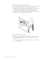
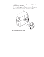
4. Note the front audio and USB assembly cables routing and remove the screw that secures the front audio and USB assembly to the chassis. Figure 37. Removing the front audio and USB assembly 5. Remove the front audio and USB assembly. 6. Route the cables for the new front audio and USB assembly through the hole in the chassis to the system board. 7. Install the new front audio and USB assembly into the chassis and secure it with the screw. 8. Connect the new front audio and USB assembly cables to the system board. See "Locating parts on the system board" on page 89. 9. Reinstall the front bezel. What to do next: v To work with another piece of hardware, go to the appropriate section. v To complete the replacement, go to "Completing the FRU replacement." Completing the FRU replacement After replacing the FRUs, you need to reinstall any removed parts, reconnect and route any internal cables, reinstall the computer cover, and reconnect any external cables, including telephone lines and power cords. Depending on the FRUs replaced, you might need to confirm the updated information in the Setup Utility program, see Chapter 6, "Using the Setup Utility program," on page 51. Note: When the power cord is first plugged in, the computer might appear to turn on for a few seconds and then turn off. This is a normal sequence to enable the computer to initialize. To reinstall the computer cover and reconnect cables to your computer: 120 Hardware Maintenance Manual
-
 1
1 -
2
-
3
-
4
-
5
-
6
-
7
-
8
-
9
-
10
-
11
-
12
-
13
-
14
-
15
-
16
-
17
-
18
-
19
-
20
-
21
-
22
-
23
-
24
-
25
-
26
-
27
-
28
-
29
-
30
-
31
-
32
-
33
-
34
-
35
-
36
-
37
-
38
-
39
-
40
-
41
-
42
-
43
-
44
-
45
-
46
-
47
-
48
-
49
-
50
-
51
-
52
-
53
-
54
-
55
-
56
-
57
-
58
-
59
-
60
-
61
-
62
-
63
-
64
-
65
-
66
-
67
-
68
-
69
-
70
-
71
-
72
-
73
-
74
-
75
-
76
-
77
-
78
-
79
-
80
-
81
-
82
-
83
-
84
-
85
-
86
-
87
-
88
-
89
-
90
-
91
-
92
-
93
-
94
-
95
-
96
-
97
-
98
-
99
-
100
-
101
-
102
-
103
-
104
-
105
-
106
-
107
-
108
-
109
-
110
-
111
-
112
-
113
-
114
-
115
-
116
-
117
-
118
-
119
-
120
-
 121
121 -
 122
122 -
 123
123 -
 124
124 -
 125
125 -
 126
126 -
 127
127 -
 128
128 -
 129
129 -
 130
130 -
 131
131 -
132
-
133
-
134
-
135
-
136
-
137
-
138
-
139
-
140
-
141
-
142
-
143
-
144
-
145
-
146
-
147
-
148
-
149
-
150
-
151
-
152
-
153
-
154
-
155
-
156
-
157
-
158
-
159
-
160
-
161
-
162
-
163
-
164
-
165
-
166
-
167
-
168
-
169
-
170
-
171
-
172
-
173
-
174
-
175
-
176
-
177
-
178
-
179
-
180
-
181
-
182
-
183
-
184
-
185
-
186
-
187
-
188
-
189
-
190
-
191
-
192
-
193
-
194
-
195
-
196
-
197
-
198
-
199
-
200
-
201
-
202
-
203
-
204
-
205
-
206
-
207
-
208
-
209
-
210
-
211
-
212
-
213
-
214
-
215
-
216
-
217
-
218
-
219
-
220
-
221
-
222
-
223
-
224
-
225
-
226
-
227
-
228
-
229
-
230
-
231
-
232
-
233
-
234
-
235
-
236
-
237
-
238
-
239
-
240
-
241
-
242
-
243
-
244
-
245
-
246
-
247
-
248
-
249
-
250
-
251
-
252
-
253
-
254
-
255
-
256
-
257
-
258
-
259
-
260
-
261
-
262
-
263
-
264
-
265
-
266
-
267
-
268
-
269
-
270
-
271
-
272
-
273
-
274
-
275
-
276
-
277
-
278
-
279
-
280
-
281
-
282
-
283
-
284
-
285
-
286
-
287
-
288
-
289
-
290
-
291
-
292
 |
 |
