Lenovo ThinkCentre A58 User Manual - Page 110
system board on the new system board., To install the microprocessor socket cover
 |
View all Lenovo ThinkCentre A58 manuals
Add to My Manuals
Save this manual to your list of manuals |
Page 110 highlights
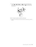
To install the microprocessor socket cover: a. Make sure the microprocessor has been removed from the microprocessor socket, and then close the microprocessor retainer and lock it into position with the small handle. b. Insert the tabs 1 of the socket cover into the hinged side of the socket, and then press the other side of the socket cover downward until the tabs 2 snap into position. Figure 19. Tabs on the microprocessor socket cover (bottom view) Figure 20. Installing the microprocessor socket cover 12. Install the new retention module on the new system board. 13. Install the heat sink and fan assembly and connect the heat sink and fan assembly cable to the microprocessor fan connector on the new system board. 14. Install the new system board into the chassis and align the screw holes with those in the chassis. Insert and tighten the screws to secure the new system board in place. 15. Install all memory modules and adapter cards removed from the failing system board on the new system board. 16. Reinstall the primary hard disk drive with the hard disk drive cage. 17. Reconnect all remaining cables to the system board. See "Locating parts on the system board" on page 89. What to do next: v To work with another piece of hardware, go to the appropriate section. v To complete the replacement, go to "Completing the FRU replacement" on page 120. 104 Hardware Maintenance Manual
-
 1
1 -
2
-
3
-
4
-
5
-
6
-
7
-
8
-
9
-
10
-
11
-
12
-
13
-
14
-
15
-
16
-
17
-
18
-
19
-
20
-
21
-
22
-
23
-
24
-
25
-
26
-
27
-
28
-
29
-
30
-
31
-
32
-
33
-
34
-
35
-
36
-
37
-
38
-
39
-
40
-
41
-
42
-
43
-
44
-
45
-
46
-
47
-
48
-
49
-
50
-
51
-
52
-
53
-
54
-
55
-
56
-
57
-
58
-
59
-
60
-
61
-
62
-
63
-
64
-
65
-
66
-
67
-
68
-
69
-
70
-
71
-
72
-
73
-
74
-
75
-
76
-
77
-
78
-
79
-
80
-
81
-
82
-
83
-
84
-
85
-
86
-
87
-
88
-
89
-
90
-
91
-
92
-
93
-
94
-
95
-
96
-
97
-
98
-
99
-
100
-
101
-
102
-
103
-
104
-
 105
105 -
 106
106 -
 107
107 -
 108
108 -
 109
109 -
 110
110 -
 111
111 -
 112
112 -
 113
113 -
 114
114 -
 115
115 -
116
-
117
-
118
-
119
-
120
-
121
-
122
-
123
-
124
-
125
-
126
-
127
-
128
-
129
-
130
-
131
-
132
-
133
-
134
-
135
-
136
-
137
-
138
-
139
-
140
-
141
-
142
-
143
-
144
-
145
-
146
-
147
-
148
-
149
-
150
-
151
-
152
-
153
-
154
-
155
-
156
-
157
-
158
-
159
-
160
-
161
-
162
-
163
-
164
-
165
-
166
-
167
-
168
-
169
-
170
-
171
-
172
-
173
-
174
-
175
-
176
-
177
-
178
-
179
-
180
-
181
-
182
-
183
-
184
-
185
-
186
-
187
-
188
-
189
-
190
-
191
-
192
-
193
-
194
-
195
-
196
-
197
-
198
-
199
-
200
-
201
-
202
-
203
-
204
-
205
-
206
-
207
-
208
-
209
-
210
-
211
-
212
-
213
-
214
-
215
-
216
-
217
-
218
-
219
-
220
-
221
-
222
-
223
-
224
-
225
-
226
-
227
-
228
-
229
-
230
-
231
-
232
-
233
-
234
-
235
-
236
-
237
-
238
-
239
-
240
-
241
-
242
-
243
-
244
-
245
-
246
-
247
-
248
-
249
-
250
-
251
-
252
-
253
-
254
-
255
-
256
-
257
-
258
-
259
-
260
-
261
-
262
-
263
-
264
-
265
-
266
-
267
-
268
-
269
-
270
-
271
-
272
-
273
-
274
-
275
-
276
-
277
-
278
-
279
-
280
-
281
-
282
-
283
-
284
-
285
-
286
-
287
-
288
-
289
-
290
-
291
-
292
 |
 |
