Lenovo ThinkCentre Edge 72z Hardware Maintenance Manual (HMM) (May 2012) - Thi - Page 113
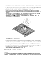
This is important when installing a new microprocessor on the system board.
 |
View all Lenovo ThinkCentre Edge 72z manuals
Add to My Manuals
Save this manual to your list of manuals |
Page 113 highlights
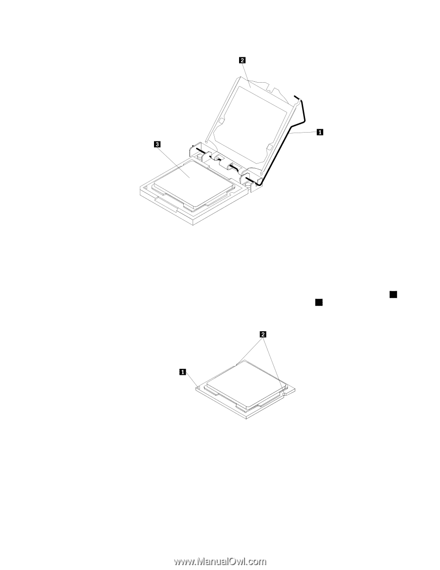
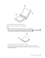
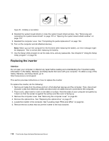
Figure 28. Opening the retainer to access the microprocessor 8. Lift the microprocessor straight up and out of the socket. Notes: a. Your microprocessor and socket might look different from the one illustrated. b. Note the orientation of the microprocessor in the socket. You can either look for the small triangle 1 on one corner of the microprocessor or note the orientation of the notches 2 on the microprocessor. This is important when installing a new microprocessor on the system board. Figure 29. Noting the orientation of the microprocessor in the socket c. Touch only the sides of the microprocessor. Do not touch the gold contacts on the bottom. d. Do not drop anything onto the microprocessor socket while it is exposed. The socket pins must be kept as clean as possible. Chapter 9. Replacing FRUs 107
-
 1
1 -
2
-
3
-
4
-
5
-
6
-
7
-
8
-
9
-
10
-
11
-
12
-
13
-
14
-
15
-
16
-
17
-
18
-
19
-
20
-
21
-
22
-
23
-
24
-
25
-
26
-
27
-
28
-
29
-
30
-
31
-
32
-
33
-
34
-
35
-
36
-
37
-
38
-
39
-
40
-
41
-
42
-
43
-
44
-
45
-
46
-
47
-
48
-
49
-
50
-
51
-
52
-
53
-
54
-
55
-
56
-
57
-
58
-
59
-
60
-
61
-
62
-
63
-
64
-
65
-
66
-
67
-
68
-
69
-
70
-
71
-
72
-
73
-
74
-
75
-
76
-
77
-
78
-
79
-
80
-
81
-
82
-
83
-
84
-
85
-
86
-
87
-
88
-
89
-
90
-
91
-
92
-
93
-
94
-
95
-
96
-
97
-
98
-
99
-
100
-
101
-
102
-
103
-
104
-
105
-
106
-
107
-
 108
108 -
 109
109 -
 110
110 -
 111
111 -
 112
112 -
 113
113 -
 114
114 -
 115
115 -
 116
116 -
 117
117 -
 118
118 -
119
-
120
-
121
-
122
-
123
-
124
-
125
-
126
-
127
-
128
-
129
-
130
-
131
-
132
-
133
-
134
-
135
-
136
-
137
-
138
-
139
-
140
-
141
-
142
 |
 |