Lenovo ThinkCentre Edge 72z Hardware Maintenance Manual (HMM) (May 2012) - Thi - Page 127
chassis. Reinstall the four screws to secure the LCD panel to the chassis.
 |
View all Lenovo ThinkCentre Edge 72z manuals
Add to My Manuals
Save this manual to your list of manuals |
Page 127 highlights
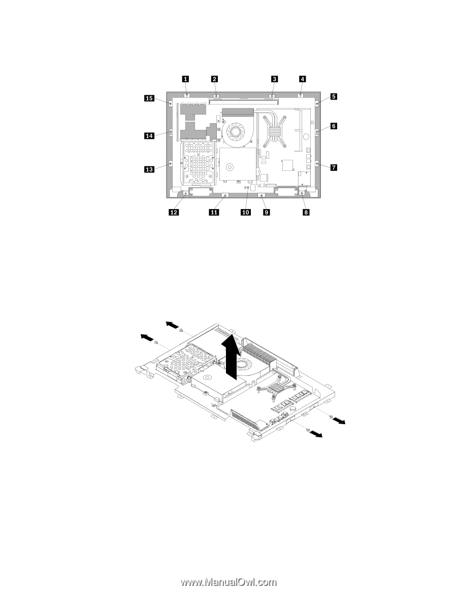
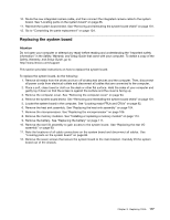
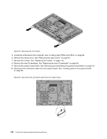
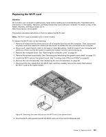
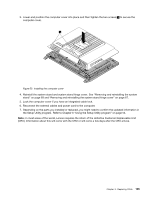
11. Remove all the 15 screws that secure the computer main bracket to the front bezel. Figure 44. Removing all the 15 screws that secure the computer main bracket to the front bezel 12. Note the locations of all cable connections that prevent you from lifting the computer main bracket, and disconnect all cables. See "Locating parts on the system board" on page 86. 13. Remove the integrated camera. See "Replacing the integrated camera" on page 116 14. Lift the computer main bracket off the front bezel. 15. Remove the four screws that secure the chassis to the LCD panel, and then lift the chassis out of the computer to get assess to the LCD panel. Figure 45. Removing the four screws that secure the LCD panel 16. Place the computer chassis over the new LCD panel so that the four screw holes align with those in the chassis. Reinstall the four screws to secure the LCD panel to the chassis. 17. Position the computer main bracket over the LCD panel. Make sure the screw holes in the computer main bracket align with those in the front bezel. 18. Reinstall all the 15 screws that secure the computer main bracket to the front bezel. Chapter 9. Replacing FRUs 121
-
 1
1 -
2
-
3
-
4
-
5
-
6
-
7
-
8
-
9
-
10
-
11
-
12
-
13
-
14
-
15
-
16
-
17
-
18
-
19
-
20
-
21
-
22
-
23
-
24
-
25
-
26
-
27
-
28
-
29
-
30
-
31
-
32
-
33
-
34
-
35
-
36
-
37
-
38
-
39
-
40
-
41
-
42
-
43
-
44
-
45
-
46
-
47
-
48
-
49
-
50
-
51
-
52
-
53
-
54
-
55
-
56
-
57
-
58
-
59
-
60
-
61
-
62
-
63
-
64
-
65
-
66
-
67
-
68
-
69
-
70
-
71
-
72
-
73
-
74
-
75
-
76
-
77
-
78
-
79
-
80
-
81
-
82
-
83
-
84
-
85
-
86
-
87
-
88
-
89
-
90
-
91
-
92
-
93
-
94
-
95
-
96
-
97
-
98
-
99
-
100
-
101
-
102
-
103
-
104
-
105
-
106
-
107
-
108
-
109
-
110
-
111
-
112
-
113
-
114
-
115
-
116
-
117
-
118
-
119
-
120
-
121
-
 122
122 -
 123
123 -
 124
124 -
 125
125 -
 126
126 -
 127
127 -
 128
128 -
 129
129 -
 130
130 -
 131
131 -
 132
132 -
133
-
134
-
135
-
136
-
137
-
138
-
139
-
140
-
141
-
142
 |
 |