Lenovo ThinkCentre M58 Hardware Maintenance Manual - Page 84
Replacing the microprocessor, Removing the heat sink, ThinkCentre Safety and Warranty Guide
 |
View all Lenovo ThinkCentre M58 manuals
Add to My Manuals
Save this manual to your list of manuals |
Page 84 highlights
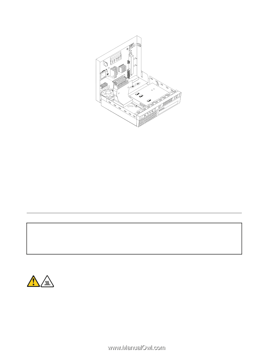
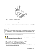
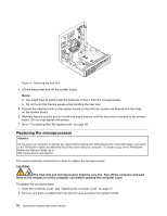
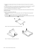
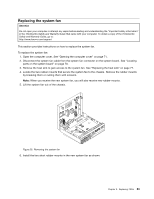
Figure 14. Removing the heat sink 4. Lift the failing heat sink off the system board. Notes: a. You might have to gently twist the heat sink to free it from the microprocessor. b. Do not touch the thermal grease while handling the heat sink. 5. Position the new heat sink on the system board so that the four screws are aligned with the holes on the system board. 6. Alternate tightening each screw a small and equal amount until the heat sink is secured to the system board. Do not over-tighten the screws. 7. Go to "Completing the FRU replacement" on page 89. Replacing the microprocessor Attention Do not open your computer or attempt any repair before reading and understanding the "Important safety information" in the ThinkCentre Safety and Warranty Guide that came with your computer. To obtain a copy of the ThinkCentre Safety and Warranty Guide, go to: http://www.lenovo.com/support This section provides instructions on how to replace the microprocessor. CAUTION: The heat sink and microprocessor might be very hot. Turn off the computer and wait three to five minutes to let the computer cool before opening the computer cover. To replace the microprocessor: 1. Open the computer cover. See "Opening the computer cover" on page 71. 2. Remove any parts or cables that may prevent your access to the system board. 78 ThinkCentre Hardware Maintenance Manual
-
 1
1 -
2
-
3
-
4
-
5
-
6
-
7
-
8
-
9
-
10
-
11
-
12
-
13
-
14
-
15
-
16
-
17
-
18
-
19
-
20
-
21
-
22
-
23
-
24
-
25
-
26
-
27
-
28
-
29
-
30
-
31
-
32
-
33
-
34
-
35
-
36
-
37
-
38
-
39
-
40
-
41
-
42
-
43
-
44
-
45
-
46
-
47
-
48
-
49
-
50
-
51
-
52
-
53
-
54
-
55
-
56
-
57
-
58
-
59
-
60
-
61
-
62
-
63
-
64
-
65
-
66
-
67
-
68
-
69
-
70
-
71
-
72
-
73
-
74
-
75
-
76
-
77
-
78
-
 79
79 -
 80
80 -
 81
81 -
 82
82 -
 83
83 -
 84
84 -
 85
85 -
 86
86 -
 87
87 -
 88
88 -
 89
89 -
90
-
91
-
92
-
93
-
94
-
95
-
96
-
97
-
98
-
99
-
100
-
101
-
102
-
103
-
104
-
105
-
106
-
107
-
108
-
109
-
110
-
111
-
112
-
113
-
114
-
115
-
116
-
117
-
118
-
119
-
120
-
121
-
122
-
123
-
124
-
125
-
126
-
127
-
128
-
129
-
130
-
131
-
132
-
133
-
134
-
135
-
136
-
137
-
138
-
139
-
140
-
141
-
142
-
143
-
144
-
145
-
146
-
147
-
148
-
149
-
150
-
151
-
152
-
153
-
154
-
155
-
156
-
157
-
158
-
159
-
160
-
161
-
162
-
163
-
164
-
165
-
166
-
167
-
168
-
169
-
170
-
171
-
172
-
173
-
174
-
175
-
176
-
177
-
178
-
179
-
180
-
181
-
182
-
183
-
184
-
185
-
186
-
187
-
188
-
189
-
190
-
191
-
192
-
193
-
194
-
195
-
196
-
197
-
198
-
199
-
200
-
201
-
202
-
203
-
204
-
205
-
206
-
207
-
208
-
209
-
210
-
211
-
212
-
213
-
214
-
215
-
216
-
217
-
218
-
219
-
220
-
221
-
222
-
223
-
224
-
225
-
226
-
227
-
228
-
229
-
230
-
231
-
232
-
233
-
234
-
235
-
236
-
237
-
238
-
239
-
240
-
241
-
242
-
243
-
244
-
245
-
246
-
247
-
248
-
249
-
250
-
251
-
252
-
253
-
254
-
255
-
256
-
257
-
258
-
259
-
260
-
261
-
262
-
263
-
264
-
265
-
266
-
267
-
268
-
269
-
270
-
271
-
272
-
273
-
274
-
275
-
276
-
277
-
278
-
279
-
280
-
281
-
282
-
283
-
284
-
285
-
286
-
287
-
288
-
289
-
290
 |
 |