Lexmark E450DN Service Manual - Page 114
LVPS/HVPS card assembly removal, Rear cover removal
 |
View all Lexmark E450DN manuals
Add to My Manuals
Save this manual to your list of manuals |
Page 114 highlights
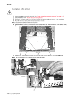
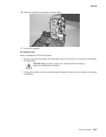
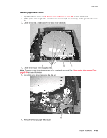
4512-630 LVPS/HVPS card assembly removal 1. Remove the rear cover. See "Rear cover removal" on page 4-6. 2. Place the printer onto its top with the back and bottom in view. Note: Be careful not to mar the finish of the printer. 3. Remove the four screws (A), the machine screw (B) and the machine screw (C). 4. Unhook the red cable (D) located in the left side frame. 5. Lift the metal cover so the connecting cables (E) and (F) can be unplugged on the side shown. 4-26 Lexmark™ E450dn
-
 1
1 -
2
-
3
-
4
-
5
-
6
-
7
-
8
-
9
-
10
-
11
-
12
-
13
-
14
-
15
-
16
-
17
-
18
-
19
-
20
-
21
-
22
-
23
-
24
-
25
-
26
-
27
-
28
-
29
-
30
-
31
-
32
-
33
-
34
-
35
-
36
-
37
-
38
-
39
-
40
-
41
-
42
-
43
-
44
-
45
-
46
-
47
-
48
-
49
-
50
-
51
-
52
-
53
-
54
-
55
-
56
-
57
-
58
-
59
-
60
-
61
-
62
-
63
-
64
-
65
-
66
-
67
-
68
-
69
-
70
-
71
-
72
-
73
-
74
-
75
-
76
-
77
-
78
-
79
-
80
-
81
-
82
-
83
-
84
-
85
-
86
-
87
-
88
-
89
-
90
-
91
-
92
-
93
-
94
-
95
-
96
-
97
-
98
-
99
-
100
-
101
-
102
-
103
-
104
-
105
-
106
-
107
-
108
-
 109
109 -
 110
110 -
 111
111 -
 112
112 -
 113
113 -
 114
114 -
 115
115 -
 116
116 -
 117
117 -
 118
118 -
 119
119 -
120
-
121
-
122
-
123
-
124
-
125
-
126
-
127
-
128
-
129
-
130
-
131
-
132
-
133
-
134
-
135
-
136
-
137
-
138
-
139
-
140
-
141
-
142
-
143
-
144
-
145
-
146
-
147
-
148
-
149
-
150
-
151
-
152
-
153
-
154
-
155
-
156
-
157
-
158
 |
 |

4-26
Lexmark™ E450dn
4512-630
LVPS/HVPS card assembly removal
1.
Remove the rear cover. See
“Rear cover removal” on page 4-6
.
2.
Place the printer onto its top with the back and bottom in view.
Note:
Be careful not to mar the finish of the printer.
3.
Remove the four screws (A), the machine screw (B) and the machine screw (C).
4.
Unhook the red cable (D) located in the left side frame.
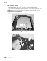
5.
Lift the metal cover so the connecting cables (E) and (F) can be unplugged on the side shown.