Lexmark E450DN Service Manual - Page 125
Paper exit guide assembly removal, Rear cover removal
 |
View all Lexmark E450DN manuals
Add to My Manuals
Save this manual to your list of manuals |
Page 125 highlights
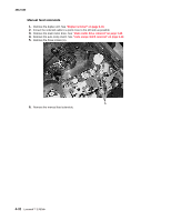
4512-630 Paper exit guide assembly removal 1. Remove the rear cover. See "Rear cover removal" on page 3-6. 2. Remove the one screw above the reversing solenoid. See "Top cover removal" on page 3-7. 3. Remove the three screws (A). A 4. Lift the back of the top cover (right side in photo) to prevent the gears on the assembly from touching other items while removing, especially the fuser mounting bracket. 5. Remove the paper exit guide assembly. Repair information 4-37
-
 1
1 -
2
-
3
-
4
-
5
-
6
-
7
-
8
-
9
-
10
-
11
-
12
-
13
-
14
-
15
-
16
-
17
-
18
-
19
-
20
-
21
-
22
-
23
-
24
-
25
-
26
-
27
-
28
-
29
-
30
-
31
-
32
-
33
-
34
-
35
-
36
-
37
-
38
-
39
-
40
-
41
-
42
-
43
-
44
-
45
-
46
-
47
-
48
-
49
-
50
-
51
-
52
-
53
-
54
-
55
-
56
-
57
-
58
-
59
-
60
-
61
-
62
-
63
-
64
-
65
-
66
-
67
-
68
-
69
-
70
-
71
-
72
-
73
-
74
-
75
-
76
-
77
-
78
-
79
-
80
-
81
-
82
-
83
-
84
-
85
-
86
-
87
-
88
-
89
-
90
-
91
-
92
-
93
-
94
-
95
-
96
-
97
-
98
-
99
-
100
-
101
-
102
-
103
-
104
-
105
-
106
-
107
-
108
-
109
-
110
-
111
-
112
-
113
-
114
-
115
-
116
-
117
-
118
-
119
-
 120
120 -
 121
121 -
 122
122 -
 123
123 -
 124
124 -
 125
125 -
 126
126 -
 127
127 -
 128
128 -
 129
129 -
 130
130 -
131
-
132
-
133
-
134
-
135
-
136
-
137
-
138
-
139
-
140
-
141
-
142
-
143
-
144
-
145
-
146
-
147
-
148
-
149
-
150
-
151
-
152
-
153
-
154
-
155
-
156
-
157
-
158
 |
 |

Repair information
4-37
4512-630
Paper exit guide assembly removal
1.
Remove the rear cover. See
“Rear cover removal” on page 3-6
.
2.
Remove the one screw above the reversing solenoid. See
“Top cover removal” on page 3-7
.
3.
Remove the three screws (A).
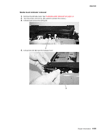
4.
Lift the back of the top cover (right side in photo) to prevent the gears on the assembly from touching other
items while removing, especially the fuser mounting bracket.
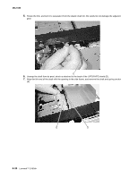
5.
Remove the paper exit guide assembly.
A