Lexmark X502n Service Manual - Page 63
Laser unit assembly service check, HVPS connection service check, and HVPS BCN1. Is cable okay? Also
 |
View all Lexmark X502n manuals
Add to My Manuals
Save this manual to your list of manuals |
Page 63 highlights
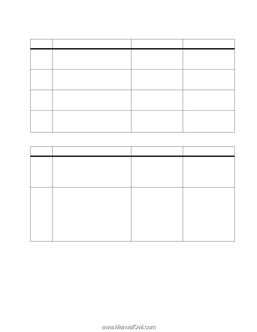
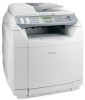
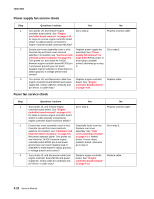
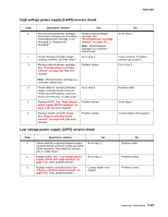
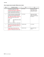
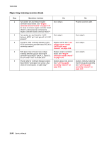
7100-XXX Laser unit assembly service check Step 1 Questions / actions Check LCN connection on laser assembly LDU board. Is connector properly connected? Yes Go to step 2. 2 Check LCN connection on engine controller Go to step 3. board. Is cable properly connected? 3 Check cable that connects engine controller Replace laser unit board LCN and LDU LCN connectors for assembly. "Upper right continuity and shorted pins. Is cable okay? rear cover removal" on page 4-17. Go to step 4. 4 Does error clear? Problem solved. HVPS connection service check No Properly connect LCN cable. If error clears, problem solved, otherwise go to step 2. Properly connect LCN cable. If error clears, problem solved, otherwise go to step 3. Replace cable. Go to step 4. Replace engine controller board. See "Engine controller board removal" on page 4-34. Step 1 2 Questions / actions Yes No Turn printer off, and remove engine controller board shield. See "Engine controller board removal" on page 4-34 for steps to remove shield. Is cable properly connected to BCN1 on the HVPS and the engine controller board HVCN connector? Turn printer off, and remove items to expose HVPS. See "High voltage power supply (HVPS) removal" on page 4-39 for steps. Check for continuity and pin shorts of cable that connects engine controller board HVCN and HVPS BCN1. Is cable okay? Also ensure that there is no damage to the connectors on both boards. Go to step 2. Replace HVPS. See "High voltage power supply (HVPS) removal" on page 4-39. Retest printer. If error clears, problem solved, otherwise turn printer off and replace engine controller board. See "Engine controller board removal" on page 4-34. Properly connect cable. Retest printer. If error clears, problem solved, otherwise go to step 2. Replace cable. Retest printer. If error clears, problem solved, otherwise turn printer off and replace engine controller board. See "Engine controller board removal" on page 4-34. Diagnostic information 2-25
-
 1
1 -
2
-
3
-
4
-
5
-
6
-
7
-
8
-
9
-
10
-
11
-
12
-
13
-
14
-
15
-
16
-
17
-
18
-
19
-
20
-
21
-
22
-
23
-
24
-
25
-
26
-
27
-
28
-
29
-
30
-
31
-
32
-
33
-
34
-
35
-
36
-
37
-
38
-
39
-
40
-
41
-
42
-
43
-
44
-
45
-
46
-
47
-
48
-
49
-
50
-
51
-
52
-
53
-
54
-
55
-
56
-
57
-
 58
58 -
 59
59 -
 60
60 -
 61
61 -
 62
62 -
 63
63 -
 64
64 -
 65
65 -
 66
66 -
 67
67 -
 68
68 -
69
-
70
-
71
-
72
-
73
-
74
-
75
-
76
-
77
-
78
-
79
-
80
-
81
-
82
-
83
-
84
-
85
-
86
-
87
-
88
-
89
-
90
-
91
-
92
-
93
-
94
-
95
-
96
-
97
-
98
-
99
-
100
-
101
-
102
-
103
-
104
-
105
-
106
-
107
-
108
-
109
-
110
-
111
-
112
-
113
-
114
-
115
-
116
-
117
-
118
-
119
-
120
-
121
-
122
-
123
-
124
-
125
-
126
-
127
-
128
-
129
-
130
-
131
-
132
-
133
-
134
-
135
-
136
-
137
-
138
-
139
-
140
-
141
-
142
-
143
-
144
-
145
-
146
-
147
-
148
-
149
-
150
-
151
-
152
-
153
-
154
-
155
-
156
-
157
-
158
-
159
-
160
-
161
-
162
-
163
-
164
-
165
-
166
-
167
-
168
-
169
-
170
-
171
-
172
-
173
-
174
-
175
-
176
-
177
-
178
-
179
-
180
-
181
-
182
-
183
-
184
-
185
-
186
-
187
-
188
-
189
-
190
-
191
-
192
-
193
-
194
-
195
-
196
-
197
-
198
-
199
-
200
-
201
-
202
-
203
-
204
-
205
-
206
-
207
-
208
-
209
-
210
-
211
-
212
-
213
-
214
-
215
-
216
-
217
-
218
-
219
-
220
-
221
-
222
-
223
-
224
-
225
-
226
-
227
-
228
-
229
-
230
-
231
-
232
-
233
-
234
-
235
-
236
-
237
-
238
-
239
-
240
-
241
-
242
-
243
-
244
 |
 |