Lexmark X502n Service Manual - Page 67
Tray empty service check
 |
View all Lexmark X502n manuals
Add to My Manuals
Save this manual to your list of manuals |
Page 67 highlights
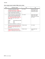
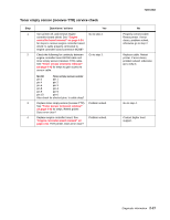
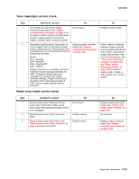
7100-XXX Tray empty service check Step 1 2 3 4 5 6 7 8 Questions / actions Yes No Remove paper tray from printer. Press bottom of spring platform latches located in rear corners of paper tray. This releases spring platform of paper tray. Ensure tray is raising paper after insertion. Is tray working properly? Ensure paper empty sensor flag swings with ease and is not broken or damaged. Is flag working properly? Turn printer off, and remove engine controller board shield. See "Engine controller board removal" on page 4-34 for steps to remove engine controller board shield. Is cable properly connected to engine controller board connector MCN9? Reconnect operator panel. Turn printer on. Touch negative lead of voltmeter to metal frame to obtain ground. Touch positive lead to engine controller board MCN9 pin 12 to ensure 5 VDC is being supplied to paper empty sensor. Is 5 VDC present? insert empty paper tray into printer. Check voltage level on MCN9 pin 14. Is 5 VDC present? Remove paper tray, fill with paper and reinsert. Check voltage level on MCN9 pin 14. Is 0 VDC present? Turn printer off. Remove paper guide (C) assembly. See "Paper guide C assembly removal" on page 4-31. Check cable for continuity that connects MCN9 pins 12, 13, and 14 to paper empty sensor. Also check for shorted pins. Is cable okay? Check cable continuity between LVPS ACN1 and engine controller board connector POCN. Also check for shorted pins. Is cable okay? Go to step 2. Go to step 3. Go to step 4. Go to step 5. Go to step 6. Replace engine controller board. See "Engine controller board removal" on page 4-34. Replace paper guide (C) assembly. See "Paper guide C assembly removal" on page 4-31. Replace LVPS. See "Low voltage power supply (LVPS) with cage removal" on page 4-40. Replace paper tray. Replace paper guide (C) assembly. See "Paper guide C assembly removal" on page 4-31. Properly connect cable. Go to step 8. Go to step 7. Replace paper guide (C) assembly. See "Paper guide C assembly removal" on page 4-31. Replace cable. Replace cable. Diagnostic information 2-29
-
 1
1 -
2
-
3
-
4
-
5
-
6
-
7
-
8
-
9
-
10
-
11
-
12
-
13
-
14
-
15
-
16
-
17
-
18
-
19
-
20
-
21
-
22
-
23
-
24
-
25
-
26
-
27
-
28
-
29
-
30
-
31
-
32
-
33
-
34
-
35
-
36
-
37
-
38
-
39
-
40
-
41
-
42
-
43
-
44
-
45
-
46
-
47
-
48
-
49
-
50
-
51
-
52
-
53
-
54
-
55
-
56
-
57
-
58
-
59
-
60
-
61
-
 62
62 -
 63
63 -
 64
64 -
 65
65 -
 66
66 -
 67
67 -
 68
68 -
 69
69 -
 70
70 -
 71
71 -
 72
72 -
73
-
74
-
75
-
76
-
77
-
78
-
79
-
80
-
81
-
82
-
83
-
84
-
85
-
86
-
87
-
88
-
89
-
90
-
91
-
92
-
93
-
94
-
95
-
96
-
97
-
98
-
99
-
100
-
101
-
102
-
103
-
104
-
105
-
106
-
107
-
108
-
109
-
110
-
111
-
112
-
113
-
114
-
115
-
116
-
117
-
118
-
119
-
120
-
121
-
122
-
123
-
124
-
125
-
126
-
127
-
128
-
129
-
130
-
131
-
132
-
133
-
134
-
135
-
136
-
137
-
138
-
139
-
140
-
141
-
142
-
143
-
144
-
145
-
146
-
147
-
148
-
149
-
150
-
151
-
152
-
153
-
154
-
155
-
156
-
157
-
158
-
159
-
160
-
161
-
162
-
163
-
164
-
165
-
166
-
167
-
168
-
169
-
170
-
171
-
172
-
173
-
174
-
175
-
176
-
177
-
178
-
179
-
180
-
181
-
182
-
183
-
184
-
185
-
186
-
187
-
188
-
189
-
190
-
191
-
192
-
193
-
194
-
195
-
196
-
197
-
198
-
199
-
200
-
201
-
202
-
203
-
204
-
205
-
206
-
207
-
208
-
209
-
210
-
211
-
212
-
213
-
214
-
215
-
216
-
217
-
218
-
219
-
220
-
221
-
222
-
223
-
224
-
225
-
226
-
227
-
228
-
229
-
230
-
231
-
232
-
233
-
234
-
235
-
236
-
237
-
238
-
239
-
240
-
241
-
242
-
243
-
244
 |
 |
