Lexmark X502n Service Manual - Page 78
Operator panel service check, USB service check, Network service check
 |
View all Lexmark X502n manuals
Add to My Manuals
Save this manual to your list of manuals |
Page 78 highlights
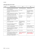
7100-XXX Operator panel service check Step 1 2 3 4 Questions / actions Yes No Is the operator panel cable properly connected to the op panel? Is the op panel cable properly connected to the RIP board connector J-PNL1? Check the op panel cable continuity. Is there continuity? Check Voltages on J-PNL1, located on the RIP card. Pin 1 voltage should measure 5V. Is it correct? Go to step 2. Go to step 3. Go to step 4. Replace the operator panel. See "Operator panel removal" on page 4-57. Properly connect the cable to the op panel. Properly connect the cable to J-PNL1. Replace the flatbed unit. See "Flatbed assembly removal" on page 4-49. Replace the system board. See "System board removal" on page 4-36. USB service check Step 1 2 3 Questions / actions Yes No Is the USB cable properly connected to the MFP and host PC? Try a different USB cable. Does this fix the issue? Connect a different device to the USB cable. Did the host PC see the device? Go to step 2. Issue fixed. Replace the RIP/system board.See "System board removal" on page 4-36. Properly connect the cable at both ends. Go to step 3. There is an issue with the host machine. Network service check Step 1 2 3 4 Questions / actions Yes Ping the MFP using the address on the MFP Go to step 3 op panel. Is it responding? Is the ethernet cable properly connected to Go to step 3. the network card RJ-45 connector? Check to see if DHCP is being used on the Go to step 4. network. Is DHCP used? Does the MFP IP address match the ports IP address on the driver? Go to step 5. 5 Have the network admin try a new network Problem resolved. cable to the MFP. Did this fix the problem? No Go to step 2. Properly connect the cable to the RJ-45 jack. Go to step 5. Have the network admin create a port on the host PC matching the IP address on the MFP. Assign the new port to the driver. Replace the system board. See "System board removal" on page 4-36. 2-40 Service Manual
-
 1
1 -
2
-
3
-
4
-
5
-
6
-
7
-
8
-
9
-
10
-
11
-
12
-
13
-
14
-
15
-
16
-
17
-
18
-
19
-
20
-
21
-
22
-
23
-
24
-
25
-
26
-
27
-
28
-
29
-
30
-
31
-
32
-
33
-
34
-
35
-
36
-
37
-
38
-
39
-
40
-
41
-
42
-
43
-
44
-
45
-
46
-
47
-
48
-
49
-
50
-
51
-
52
-
53
-
54
-
55
-
56
-
57
-
58
-
59
-
60
-
61
-
62
-
63
-
64
-
65
-
66
-
67
-
68
-
69
-
70
-
71
-
72
-
 73
73 -
 74
74 -
 75
75 -
 76
76 -
 77
77 -
 78
78 -
 79
79 -
 80
80 -
 81
81 -
 82
82 -
 83
83 -
84
-
85
-
86
-
87
-
88
-
89
-
90
-
91
-
92
-
93
-
94
-
95
-
96
-
97
-
98
-
99
-
100
-
101
-
102
-
103
-
104
-
105
-
106
-
107
-
108
-
109
-
110
-
111
-
112
-
113
-
114
-
115
-
116
-
117
-
118
-
119
-
120
-
121
-
122
-
123
-
124
-
125
-
126
-
127
-
128
-
129
-
130
-
131
-
132
-
133
-
134
-
135
-
136
-
137
-
138
-
139
-
140
-
141
-
142
-
143
-
144
-
145
-
146
-
147
-
148
-
149
-
150
-
151
-
152
-
153
-
154
-
155
-
156
-
157
-
158
-
159
-
160
-
161
-
162
-
163
-
164
-
165
-
166
-
167
-
168
-
169
-
170
-
171
-
172
-
173
-
174
-
175
-
176
-
177
-
178
-
179
-
180
-
181
-
182
-
183
-
184
-
185
-
186
-
187
-
188
-
189
-
190
-
191
-
192
-
193
-
194
-
195
-
196
-
197
-
198
-
199
-
200
-
201
-
202
-
203
-
204
-
205
-
206
-
207
-
208
-
209
-
210
-
211
-
212
-
213
-
214
-
215
-
216
-
217
-
218
-
219
-
220
-
221
-
222
-
223
-
224
-
225
-
226
-
227
-
228
-
229
-
230
-
231
-
232
-
233
-
234
-
235
-
236
-
237
-
238
-
239
-
240
-
241
-
242
-
243
-
244
 |
 |
