MSI rc410M2 User Guide - Page 26
ATX 12V Power Connector: JPW1
 |
View all MSI rc410M2 manuals
Add to My Manuals
Save this manual to your list of manuals |
Page 26 highlights
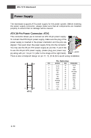
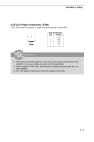
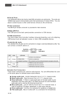
Hardware Setup ATX 12V Power Connector: JPW1 This 12V power connector is used to provide power to the CPU. 2 1 4 3 JPW1 Pin Definition PIN SIGNAL 1 GND 2 GND 3 12V 4 12V Important 1. These two connectors connect to the ATX power supply and have to work together to ensure stable operation of the mainboard. 2. Power supply of 350 watts (and above) is highly recommended for system stability. 3. ATX 12V power connection should be greater than 18A. 2-11
-
 1
1 -
2
-
3
-
4
-
5
-
6
-
7
-
8
-
9
-
10
-
11
-
12
-
13
-
14
-
15
-
16
-
17
-
18
-
19
-
20
-
 21
21 -
 22
22 -
 23
23 -
 24
24 -
 25
25 -
 26
26 -
 27
27 -
 28
28 -
 29
29 -
 30
30 -
 31
31 -
32
-
33
-
34
-
35
-
36
-
37
-
38
-
39
-
40
-
41
-
42
-
43
-
44
-
45
-
46
-
47
-
48
-
49
-
50
-
51
-
52
-
53
-
54
-
55
-
56
-
57
-
58
-
59
-
60
-
61
-
62
-
63
-
64
-
65
-
66
-
67
-
68
-
69
-
70
-
71
-
72
-
73
-
74
-
75
-
76
-
77
-
78
-
79
-
80
-
81
-
82
-
83
-
84
-
85
-
86
-
87
-
88
-
89
-
90
-
91
-
92
-
93
-
94
-
95
-
96
-
97
-
98
-
99
-
100
-
101
-
102
-
103
-
104
-
105
-
106
-
107
 |
 |

2-11
Hardware Setup
ATX 12V Power Connector: JPW1
This 12V power connector is used to provide power to the CPU.
Important
1. These two connectors connect to the ATX power supply and have to work
together to ensure stable operation of the mainboard.
2. Power supply of 350 watts (and above) is highly recommended for sys-
tem stability.
3. ATX 12V power connection should be greater than 18A.
PIN
1
2
3
4
Pin Definition
SIGNAL
GND
GND
12V
12V
JPW1
2
4
1
3