MSI rc410M2 User Guide - Page 38
FWH/LPC Debugging Connector: JLPC1 - international
 |
View all MSI rc410M2 manuals
Add to My Manuals
Save this manual to your list of manuals |
Page 38 highlights
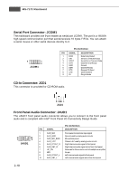
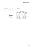
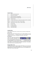
Hardware Setup FWH/LPC Debugging Connector: JLPC1 The connector is for internal debugging only. 13 1 14 2 JLPC1 Pin Definition PIN SIGNAL PIN SIGNAL 1 LCLK 2 Key (no pin) 3 LRST# 4 VCC3 5 LAD0 6 FID0_LRST 7 LAD1 8 VCC5 9 LAD2 10 Key(no pin) 11 LAD3 12 GND 13 LFRAME# 14 GND 2-23
-
 1
1 -
2
-
3
-
4
-
5
-
6
-
7
-
8
-
9
-
10
-
11
-
12
-
13
-
14
-
15
-
16
-
17
-
18
-
19
-
20
-
21
-
22
-
23
-
24
-
25
-
26
-
27
-
28
-
29
-
30
-
31
-
32
-
 33
33 -
 34
34 -
 35
35 -
 36
36 -
 37
37 -
 38
38 -
 39
39 -
 40
40 -
 41
41 -
 42
42 -
 43
43 -
44
-
45
-
46
-
47
-
48
-
49
-
50
-
51
-
52
-
53
-
54
-
55
-
56
-
57
-
58
-
59
-
60
-
61
-
62
-
63
-
64
-
65
-
66
-
67
-
68
-
69
-
70
-
71
-
72
-
73
-
74
-
75
-
76
-
77
-
78
-
79
-
80
-
81
-
82
-
83
-
84
-
85
-
86
-
87
-
88
-
89
-
90
-
91
-
92
-
93
-
94
-
95
-
96
-
97
-
98
-
99
-
100
-
101
-
102
-
103
-
104
-
105
-
106
-
107
 |
 |

2-23
Hardware Setup
FWH/LPC Debugging Connector: JLPC1
The connector is for internal debugging only.
Pin Definition
PIN
SIGNAL
PIN
SIGNAL
1
LCLK
2
Key (no pin)
3
LRST#
4
VCC3
5
LAD0
6
FID0_LRST
7
LAD1
8
VCC5
9
LAD2
10
Key (no pin)
11
LAD3
12
GND
13
LFRAME#
14
GND
JLPC1
1
13
14
2