MSI rc410M2 User Guide - Page 35
Front Panel Connectors: JFP1, Front USB Connectors: JUSB1 / JUSB2 / JUSB3
 |
View all MSI rc410M2 manuals
Add to My Manuals
Save this manual to your list of manuals |
Page 35 highlights
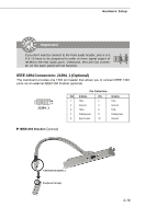
MS-7173 Mainboard Front Panel Connectors: JFP1 The mainboard provides one front panel connector for electrical connection to the front panel switches and LEDs. The JFP1 is compliant with Intel® Front Panel I/O Connectivity Design Guide. Power Power LED Switch 2 10 1 9 HDD Reset LED Switch JFP1 Pin Definition PIN SIGNAL DESCRIPTION 1 HD_LED_P Hard disk LED pull-up 2 FP PW R/SLP MSG LED pull-up 3 HD_LED_N Hard disk active LED 4 FP PW R/SLP MSG LED pull-up 5 RST_SW_N Reset Switch low reference pull-down to GND 6 PWR_SW_P Power Switch high reference pull-up 7 RST_SW_P Reset Switch high reference pull-up 8 PWR_SW_N Power Switch low reference pull-down to GND 9 RSVD_DNU Reserved. Do not use. Front USB Connectors: JUSB1 / JUSB2 / JUSB3 The mainboard provides three standard USB 2.0 pin headers JUSB1 & JUSB2 & JUSB3. USB 2.0 technology increases data transfer rate up to a maximum throughput of 480Mbps, which is 40 times faster than USB 1.1, and is ideal for connecting highspeed USB interface peripherals such as USB HDD, digital cameras, MP3 players, printers, modems and the like. 2 10 1 9 JUSB1 / JUSB2 / JUSB3 Pin Definition PIN SIGNAL 1 VCC 3 USB0- 5 USB0+ 7 GND 9 Key (no pin) PIN SIGNAL 2 VCC 4 USB1- 6 USB1+ 8 GND 10 USBOC USB 2.0 Bracket (Optional) 2-20 Connected to JUSB1/JUSB2/JUSB3
-
 1
1 -
2
-
3
-
4
-
5
-
6
-
7
-
8
-
9
-
10
-
11
-
12
-
13
-
14
-
15
-
16
-
17
-
18
-
19
-
20
-
21
-
22
-
23
-
24
-
25
-
26
-
27
-
28
-
29
-
 30
30 -
 31
31 -
 32
32 -
 33
33 -
 34
34 -
 35
35 -
 36
36 -
 37
37 -
 38
38 -
 39
39 -
 40
40 -
41
-
42
-
43
-
44
-
45
-
46
-
47
-
48
-
49
-
50
-
51
-
52
-
53
-
54
-
55
-
56
-
57
-
58
-
59
-
60
-
61
-
62
-
63
-
64
-
65
-
66
-
67
-
68
-
69
-
70
-
71
-
72
-
73
-
74
-
75
-
76
-
77
-
78
-
79
-
80
-
81
-
82
-
83
-
84
-
85
-
86
-
87
-
88
-
89
-
90
-
91
-
92
-
93
-
94
-
95
-
96
-
97
-
98
-
99
-
100
-
101
-
102
-
103
-
104
-
105
-
106
-
107
 |
 |
