Marantz AV8003 AV8003 User Manua - Page 10

Rear Panel - mm8003

Page 10 highlights

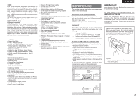
ENGLISH NAMES AND FUNCTION CONNECTIONS SETUP BASIC OPERATION REAR PANEL qw e rt y @6 @5 @4 @3 INPUT 1(TV) INPUT 2(DVD) FM (75Ω) GND AM ANTENNA INPUT 1(TV) COMPONENT Y CB/PB CR/PR VIDEO INPUT 3(VCR1) INPUT 2(DVD) INPUT 3(VCR1) INPUT 4(DSS/VCR2) Y CB/PB CR/PR Y INPUT 4(DSS / VCR2) OUTPUT 1 OUTPUT 2 OUT PUT 1 CB/PB CR/PR OUT PUT 2 R SR SBR SW L SL 3 1 2 SBL R C 3 1 2 3 1 2 L 3 1 2 3 1 2 SR 3 1 2 TV(1) DVD(2) VCR1(3) DSS/VCR2(4) MONITOR ZONE OUT OUT TV(1) DVD(2) VCR1(3) IN OUT VIDEO 4 5 IN OUT IN OUT REMOTE 6 COAX. IN 1 2 3 DIGITAL IN TV DVD OPT. DIGITAL OUT MAIN VCR1 DSS/VCR2 OUT ZONE TAPE S-VIDEO DC OUT 1 1 IR FLASHER RECEIVER IN IN 2 2 CD/CDR EMITTER OUT ZONE OUT DSS/VCR2(4) IN OUT MONI. OUT UNBALANCED CD/CDR BALANCED IN PUSH PUSH CONNECTION 1 GND 2 1 2 HOT(+) 3 3 COLD(-) RS-232C SBR SBL SW BALANCED PRE OUT SIRIUS SPEAKER C ON OFF 3 2 1 R L SL 3 2 1 UNBALANCED BALANCED L SBL SELECTOR C AC IN 3 1 2 SL 3 1 2 C L MODEL NO. AV8003 7.1CH IN R IN OUT IN OUT IN OUT IN OUT A AUDIO B R SR (AUX) SBR SW CONNECTION 1 GND 2 HOT(+) 1 2 3 COLD(-) 3 NETWORK @0 e @2 @1 !9!8 !7 !6 !5 !4 !3 !2!1 !0 o i u q FM antenna terminal (75 ohms) Connect an external FM antenna with a coaxial cable, or a cable network FM source. AM antenna and ground terminals Connect the supplied AM loop antenna. Use the terminals marked "AM" and "GND". The supplied AM loop antenna will provide good AM reception in most areas. Position the loop antenna until you hear the best reception. w COMPONENT VIDEO INPUT/ OUTPUT If your DVD player or other device has component video connectors, be sure to connect them to these component video connectors on the unit. This unit has 4 component video input connectors to obtain the color information (Y, CB, CR) directly from the recorded DVD signal or other video component and two component video outputs connector to output it directly into the matrix decoder of the display device. By sending the pure DVD component video signal directly, the DVD signal forgoes the extra processing that normally would degrade the image. The result is vastly increased image quality, with incredibly life like colors and crisp detail. The Monitor Out 2 terminal is also used for ZONE output. e Zone Outputs (Audio output A/B, Video) These are the audio and video output jacks for the Multi zone. Connect these jacks to optional audio power amplifiers or video display devices to listen and view the source selected by the zone system in a remote room. r MONITOR OUT These are monitor outputs and each one includes both composite video and S-video configurations. When connecting two video monitors or televisions, be aware that the OSD interface can be used with both MONITOR OUT connections. t UNBALANCED PREOUT (L, R, SL, SR, SBL, SBR, C) Connect the L (front left), R (front right), C (center), SL (Surround left), SR (Surround right), SBL (Surround back left), and SBR (Surround back right) terminals to the unbalanced input terminals of a power amp such as the MM8003. y BALANCED PREOUT (L, R,SL, SR, SBL, SBR, C) Connect the L (front left), R (front right), C (center), SL (Surround left), SR (Surround right), SBL (Surround back left), and SBR (Surround back right) terminals to the balanced input terminals of a power amp such as the MM8003. u NETWORK Connect to a network device such as a router or hub. This allows you to play back music, photos, and movie files stored on a connected network device. i Subwoofer Output These are subwoofer outputs and each one includes both unbalanced and balanced jack configulations. Connect this jack to the line level input of a powered subwoofer. o SPEAKER C switch Set to ON to connect a bi-amp to this unit or set to OFF for normal connection (surround back and zone speakers). (See page 19) !0 SIRIUS terminal Connect the SiriusConnect Home tuner. See page 17 for connecting information. !1 XM terminal Connect the XM Mini Tuner and Home Dock. See page 17 for connecting information. !2 RS-232C The RS-232C port is to be used in connection with an external controller to control the operation of the unit by using an external device. The RS-232C port may also be used in the future to update the operating software of the unit so that it will be able to support new digital audio formats and the like as they are introduced. !3 AC INLET Plug the supplied power cable into this AC INLET and then into the power outlet on the wall. This unit can be powered by 120V AC only. !4 CD/CDR Input Selection Switch Switches between BALANCED and UNBALANCED for the CD/CDR IN terminals. Notes: • Always set the input selection before turning on the power. Equipment failure may result If the input selection is switched while the power is on. • Audio may not be output from the main unit if the input to the unit differs from the setting of the Input Selection Switch. !5 BALANCED CD/CDR IN Connect to the balanced output terminal of a Super Audio CD Player or similar player. The UNBALANCED CD/CDR input terminals are the CD/CDR IN terminals in @.3 Note: Do not connect to the BALANCED and UNBALANCED terminals at the same time. !6 7.1 CHANNEL or AUX INPUT By connecting a DVD Audio player, Super Audio CD multichannel player, or other components that has a multichannel port, you can playback the audio with 5.1 channel or 7.1 channel outputs. !7 EMITTER OUT The signals input to the IR RECEIVER IN terminals are output to this terminal. External devices can be controlled by connecting them to this terminal. !8 IR RECEIVER IN Connect to an external IR receiver. !9 FLASHER IN (Flasher input terminal) These terminals are to control the unit from each zone. Connect the control signal from a Keypad, etc. @0 DC TRIGGER output terminal Connect a device that needs to be triggered by DC under certain conditions (screen, power strip, etc...) Use the system OSD setup menu to determine the conditions by which these jack will be active. (See page 36) Note: • This output voltage is for (status) control only, It is not sufficient for drive capability. 7 ADVANCED OPERATION REMOTE CONTROLLER TROUBLESHOOTING OTHERS

  • 1
  • 2
  • 3
  • 4
  • 5
  • 6
  • 7
  • 8
  • 9
  • 10
  • 11
  • 12
  • 13
  • 14
  • 15
  • 16
  • 17
  • 18
  • 19
  • 20
  • 21
  • 22
  • 23
  • 24
  • 25
  • 26
  • 27
  • 28
  • 29
  • 30
  • 31
  • 32
  • 33
  • 34
  • 35
  • 36
  • 37
  • 38
  • 39
  • 40
  • 41
  • 42
  • 43
  • 44
  • 45
  • 46
  • 47
  • 48
  • 49
  • 50
  • 51
  • 52
  • 53
  • 54
  • 55
  • 56
  • 57
  • 58
  • 59
  • 60
  • 61
  • 62
  • 63
  • 64
  • 65
  • 66
  • 67
  • 68
  • 69
  • 70
  • 71
  • 72
  • 73
  • 74
  • 75
  • 76
  • 77
  • 78
  • 79
  • 80
  • 81
  • 82
  • 83
  • 84
  • 85
  • 86
  • 87
  • 88
  • 89
  • 90
  • 91
  • 92
  • 93
  • 94
  • 95
  • 96
  • 97
  • 98
  • 99
  • 100
  • 101
  • 102
  • 103
  • 104
  • 105
  • 106
  • 107

CONNECTIONS
NAMES AND
FUNCTION
SETUP
BASIC
OPERATION
ADVANCED
OPERATION
REMOTE
CONTROLLER
TROUBLESHOOTING
OTHERS
ENGLISH
7
y
BALANCED PREOUT
(L, R,SL, SR, SBL, SBR, C)
Connect the L (front left), R (front right), C (center), SL
(Surround left), SR (Surround right), SBL (Surround
back left), and SBR (Surround back right) terminals
to the balanced input terminals of a power amp such
as the MM8003.
u
NETWORK
Connect to a network device such as a router or
hub.
This allows you to play back music, photos, and
movie files stored on a connected network device.
i
Subwoofer Output
These are subwoofer outputs and each one includes
both unbalanced and balanced jack configulations.
Connect this jack to the line level input of a powered
subwoofer.
o
SPEAKER C switch
Set to ON to connect a bi-amp to this unit or set to
OFF for normal connection (surround back and zone
speakers). (See page 19)
!
0
SIRIUS terminal
Connect the SiriusConnect Home tuner.
See page 17 for connecting information.
!
1
XM terminal
Connect the XM Mini Tuner and Home Dock.
See page 17 for connecting information.
!
2
RS-232C
The RS-232C port is to be used in connection with an
external controller to control the operation of the unit
by using an external device.
The RS-232C port may also be used in the future to
update the operating software of the unit so that it will
be able to support new digital audio formats and the
like as they are introduced.
!
3
AC INLET
Plug the supplied power cable into this AC INLET
and then into the power outlet on the wall.
This unit can be powered by 120V AC only.
!
4
CD/CDR Input Selection Switch
Switches between BALANCED and UNBALANCED
for the CD/CDR IN terminals.
Notes:
• Always set the input selection before turning on the
power. Equipment failure may result If the input
selection is switched while the power is on.
• Audio may not be output from the main unit if the
input to the unit differs from the setting of the Input
Selection Switch.
!
5
BALANCED CD/CDR IN
Connect to the balanced output terminal of a Super
Audio CD Player or similar player.
The UNBALANCED CD/CDR input terminals are
the CD/CDR IN terminals in
@
3
.
Note:
Do not connect to the BALANCED and
UNBALANCED terminals at the same time.
!
6
7.1 CHANNEL or AUX INPUT
By connecting a DVD Audio player, Super Audio CD
multichannel player, or other components that has a
multichannel port, you can playback the audio with
5.1 channel or 7.1 channel outputs.
!
7
EMITTER OUT
The signals input to the IR RECEIVER IN terminals
are output to this terminal. External devices can be
controlled by connecting them to this terminal.
!
8
IR RECEIVER IN
Connect to an external IR receiver.
!
9
FLASHER IN (Flasher input terminal)
These terminals are to control the unit from each zone.
Connect the control signal from a Keypad, etc.
@
0
DC TRIGGER output terminal
Connect a device that needs to be triggered by DC
under certain conditions (screen, power strip, etc…)
Use the system OSD setup menu to determine the
conditions by which these jack will be active.
(See page 36)
Note:
• This output voltage is for (status) control only, It is
not sufficient for drive capability.
REAR PANEL
e
Zone Outputs
(Audio output A/B, Video)
These are the audio and video output jacks for the
Multi zone.
Connect these jacks to optional audio power
amplifiers or video display devices to listen and view
the source selected by the zone system in a remote
room.
r
MONITOR OUT
These are monitor outputs and each one includes
both composite video and S-video configurations.
When connecting two video monitors or televisions,
be aware that the OSD interface can be used with
both MONITOR OUT connections.
t
UNBALANCED PREOUT
(L, R, SL, SR, SBL, SBR, C)
Connect the L (front left), R (front right), C (center), SL
(Surround left), SR (Surround right), SBL (Surround
back left), and SBR (Surround back right) terminals
to the unbalanced input terminals of a power amp
such as the MM8003.
q
FM antenna terminal (75 ohms)
Connect an external FM antenna with a coaxial
cable, or a cable network FM source.
AM antenna and ground terminals
Connect the supplied AM loop antenna. Use the
terminals marked “AM” and “GND”. The supplied AM
loop antenna will provide good AM reception in most
areas. Position the loop antenna until you hear the
best reception.
w
COMPONENT VIDEO INPUT/
OUTPUT
If your DVD player or other device has component
video connectors, be sure to connect them to these
component video connectors on the unit. This unit
has 4 component video input connectors to obtain
the color information (Y, C
B
, C
R
) directly from the
recorded DVD signal or other video component and
two component video outputs connector to output it
directly into the matrix decoder of the display device.
By sending the pure DVD component video signal
directly, the DVD signal forgoes the extra processing
that normally would degrade the image. The result is
vastly increased image quality, with incredibly life like
colors and crisp detail.
The Monitor Out 2 terminal is also used for ZONE
output.
L
SR
SR
SL
SL
R
R
SR
SR
SL
SL
SW
SW
C
SBR
SBR
SBL
SBL
L
SBL
SBL
SW
SW
C
SBR
SBR
FM
FM
(
75
75
Ω
)
GND
GND
AM
AM
ANTENNA
ANTENNA
OUT
OUT
PUT
PUT
1
OUT
OUT
PUT
PUT
2
INPUT 3
INPUT 3
(
VCR1
VCR1
)
OUTPUT 1
OUTPUT 1
OUTPUT 2
OUTPUT 2
INPUT 1
INPUT 1
(
TV
TV
)
INPUT 4
INPUT 4
(
DSS/VCR2
DSS/VCR2
)
INPUT 2
INPUT 2
(
DVD
DVD
)
COMPONENT
COMPONENT
VIDEO
VIDEO
C
B
/
P
B
C
R
/
P
R
C
R
/
P
R
C
R
/
P
R
C
B
/
P
B
C
B
/
P
B
Y
Y
Y
INPUT 1
INPUT 1
(
TV
TV
)
INPUT 4
INPUT 4
(
DSS
DSS
/
VCR2
VCR2
)
INPUT 3
INPUT 3
(
VCR1
VCR1
)
INPUT 2
INPUT 2
(
DVD
DVD
)
RS-232C
RS-232C
SPEAKER C
SPEAKER C
SIRIUS
SIRIUS
NETWORK
NETWORK
ON
ON
OFF
OFF
1
3
CONNECTION
GND
HOT(+)
COLD(
-
)
3
2
1
2
AC IN
AC IN
OUT
OUT
IN
IN
IN
IN
OUT
OUT
VIDEO
VIDEO
MONITOR
MONITOR
OUT
OUT
DVD
DVD
(2)
DSS/VCR2
DSS/VCR2
(4)
TV
TV
(1)
ZONE
ZONE
OUT
OUT
VCR1
VCR1
(3)
DVD
DVD
(2)
TV
TV
(1)
2
1
FLASHER
FLASHER
IN
IN
IR
IR
RECEIVER
RECEIVER
IN
IN
6
COAX.
COAX.
5
4
OUT
OUT
IN
IN
1
2
EMITTER
EMITTER
OUT
OUT
SELECTOR
SELECTOR
DC OUT
DC OUT
R
L
OUT
OUT
R
OUT
OUT
L
TAPE
TAPE
OUT
OUT
IN
IN
R
OUT
OUT
L
DSS/VCR2
DSS/VCR2
AUDIO
AUDIO
BALANCED
BALANCED
PRE OUT
PRE OUT
UNBALANCED
UNBALANCED
TV
TV
IN
IN
SR
SR
VCR1
VCR1
IN
IN
DVD
DVD
SL
SL
SBR
SBR
SBL
SBL
SW
SW
C
A
B
7.1CH
7.1CH
IN
IN
(
AUX
AUX
)
3
2
1
OPT.
OPT.
MODEL NO. AV8003
MODEL NO. AV8003
DIGITAL IN
DIGITAL IN
DIGITAL OUT
DIGITAL OUT
MAIN
MAIN
ZONE
ZONE
CD/CDR
CD/CDR
IN
IN
REMOTE
REMOTE
1
2
3
BALANCED
BALANCED
UNBALANCED
UNBALANCED
IN
IN
OUT
OUT
S-VIDEO
S-VIDEO
IN
IN
OUT
OUT
DSS/VCR2
DSS/VCR2
(4)
VCR1
VCR1
(3)
MONI. OUT
MONI. OUT
CD/CDR BALANCED IN
CD/CDR BALANCED IN
ZONE OUT
ZONE OUT
CONNECTION
GND
HOT(+)
COLD(
-
)
3
2
1
3
1
2
3
1
2
3
1
2
3
1
2
3
1
2
3
1
2
3
1
2
3
1
2
3
1
2
3
1
2
PUSH
PUSH
q
w
t
y
u
!3
i
!6
@1
@2
e
@0
o
!0
!2
!1
!5
!4
!7
!8
!9
@
3
@
6
@
4
@
5
r
e