Marantz AV8003 AV8003 User Manua - Page 23
Connecting Other Equipment, Connections With Network Devices
 |
View all Marantz AV8003 manuals
Add to My Manuals
Save this manual to your list of manuals |
Page 23 highlights
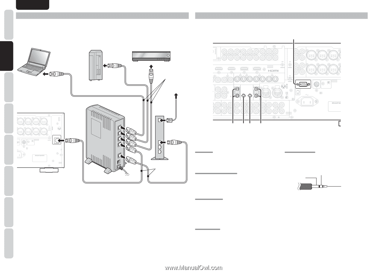
ENGLISH NAMES AND FUNCTION CONNECTIONS SETUP BASIC OPERATION ADVANCED OPERATION CONNECTIONS WITH NETWORK DEVICES As shown in the diagram, music, images, and movie files stored on a network device can be played by connecting to a network device such as a router or a hub. Use a LAN cable when connecting a network device to the NETWORK terminal of this unit. For settings necessary to use the network and method of operation, see the NETWORK User Guide. Computer Network HDD that supports DLNA HDD recorder that supports DLNA Windows Media Player 11 or server software that supports DLNA Straight LAN cable (purchase separately) To the Internet connection L SL SBL R L SR SL C SBR SBL SW C UNBALANCED BALANCED PRE OUT RS-232C SIRIUS SPEAKER C ON OFF AC IN CONNECTION 1 GND 2 HOT(+) 1 2 3 COLD(-) 3 NETWORK MODEL NO. AV8003 Router LAN WAN Modem Straight LAN cable (purchase separately) Note: • The unit's network connector supports 10BASE-T/100BASE-TX. Use a 100BASE-TX connection to ensure smooth playback. • Use a straight LAN cable that is category 5 or higher. • If there are not enough LAN connectors, add a hub (purchase separately) to the router. • The term network device refers to the following devices. - Hard disk with a built-in DLNA server function (LAN connection type) - HDD recorder or audio system that supports DLNA - A computer can be used when either of the following server software programs is installed. • Windows Media Player 11 • Server software that supports DLNA CONNECTING OTHER EQUIPMENT a INPUT 1(TV) INPUT 2(DVD) COMPONENT Y CB/PB CR/PR VIDEO INPUT 3(VCR1) INPUT 3(VCR1) INPUT 4(DSS/VCR2) Y CB/PB CR/PR Y INPUT 4(DSS / VCR2) OUTPUT 1 OUTPUT 2 OUT PUT 1 CB/PB CR/PR OUT PUT 2 R SR SBR SW L SL SBL R C L SR DSS/VCR2(4) MONITOR ZONE OUT OUT TV(1) DVD(2) VCR1(3) IN OUT IN OUT REMOTE COAX. IN OPT. DIGITAL OUT MAIN DSS/VCR2 OUT ZONE TAPE S-VIDEO DC OUT 1 1 IR FLASHER RECEIVER IN IN 2 CD/CDR 2 EMITTER OUT ZONE OUT DSS/VCR2(4) IN OUT MONI. OUT UNBALANCED CD/CDR BALANCED IN PUSH PUSH CONNECTION 1 GND 2 1 2 HOT(+) 3 3 COLD(-) RS-232C SBR SBL SW BALANCED PRE OUT SIRIUS SPEAKER C ON OFF R L SL L SBL UNBALANCED BALANCED SELECTOR C AC IN 7.1CH IN MODEL NO. AV8003 IN OUT IN OUT IN OUT A AUDIO B R SR (AUX) SBR SW s fg d a RS232C Connect an external control device or other device for servicing. (Use a straight cable for the connection.) s DC OUT (DC TRIGGER) External devices can be controlled from the unit by connecting them to the DC OUT terminal (12 V 44mA max). g IR RECEIVER IN This unit can be operated by remote controller without using the internal IR receiver, by connecting an external IR receiver. +12V GND Signal d EMITTER OUT Outputs the remote control signal input to the IR RECEIVER IN terminals. External components can be controlled by connecting them to the EMITTER OUT terminal. f FLASHER IN This unit can be controlled by connecting a control box or other control device to this unit. An IR receiver is connected as shown above. Caution: • Wrongly connecting an IR receiver or connecting an IR receiver of the wrong voltage can damage the unit, therefore do not do this. • 50 mA of current are supplied to the device connected to the IR RECEIVER IN terminal. • Connecting a device that requires more than 50 mA of current to this unit will damage this unit. Before using other devices, carefully check the specifications of those devices. 20 REMOTE CONTROLLER TROUBLESHOOTING OTHERS
-
 1
1 -
2
-
3
-
4
-
5
-
6
-
7
-
8
-
9
-
10
-
11
-
12
-
13
-
14
-
15
-
16
-
17
-
 18
18 -
 19
19 -
 20
20 -
 21
21 -
 22
22 -
 23
23 -
 24
24 -
 25
25 -
 26
26 -
 27
27 -
 28
28 -
29
-
30
-
31
-
32
-
33
-
34
-
35
-
36
-
37
-
38
-
39
-
40
-
41
-
42
-
43
-
44
-
45
-
46
-
47
-
48
-
49
-
50
-
51
-
52
-
53
-
54
-
55
-
56
-
57
-
58
-
59
-
60
-
61
-
62
-
63
-
64
-
65
-
66
-
67
-
68
-
69
-
70
-
71
-
72
-
73
-
74
-
75
-
76
-
77
-
78
-
79
-
80
-
81
-
82
-
83
-
84
-
85
-
86
-
87
-
88
-
89
-
90
-
91
-
92
-
93
-
94
-
95
-
96
-
97
-
98
-
99
-
100
-
101
-
102
-
103
-
104
-
105
-
106
-
107
 |
 |