Maytag MMMF6030PZ Owners Manual - Page 6
Location Requirements, Product Dimensions, Installation Dimensions, Special Requirements
 |
View all Maytag MMMF6030PZ manuals
Add to My Manuals
Save this manual to your list of manuals |
Page 6 highlights
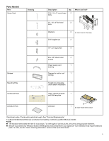
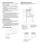
Location Requirements Check the opening where the microwave oven will be installed. The location must provide: � Minimum installation dimensions. See the "Installation Dimensions" illustration. � Minimum one 2" x 4" (5.1 x 10.2 cm) wood wall stud and minimum 3/8" (1 cm) thickness drywall or plaster/lath within cabinet opening. � Support for weight of 150 lbs (68 kg) which includes microwave oven and items placed inside the microwave oven and upper cabinet. � Grounded electrical outlet inside upper cabinet. See the "Electrical Requirements" section. NOTE: � Some models have a pocket handle. If installing the microwave near a right side wall, make sure there is at least 3" (7.6 cm) of clearance between wall and microwave oven so you can grab the handle integrated inside the door. � Some cabinet and building materials are not designed to withstand the heat produced by the microwave oven for cooking. Check with your builder or cabinet supplier to make sure that the materials used will not discolor, delaminate, or sustain other damages. Special Requirements For Wall Venting Installation Only: � Cutout must be free of any obstructions so that the vent fit properly and the damper blade opens freely and fully. For Roof Venting Installation Only: � If you are using a rectangular-to-round transition piece, the 3" (7.6 cm) clearance needs to exist above the microwave oven so that the damper blade can open freely and fully. See "Rectangular to Round Transition" illustration in the "Venting Design Specifications" section. Product Dimensions B A C A. 297/8" (76.1 cm) B. 177/8" (45.4 cm) C. 121/8" (31.3 cm) Installation Dimensions NOTE: The grounded 3 prong outlet must be inside the upper cabinet. See the "Electrical Requirements" section. A B C G E D F A. 2" x 4" (5.1 cm x 10.2 cm) wall stud B. Grounded 3 prong outlet C. Upper cabinet depth (with door) 12" (30.5 cm) to 13" (33 cm)*** D. 36" (91.4 cm) recommended* 30" (76.2 cm) typical** E. 30" (76.2 cm) minimum F. 72" (182.8 cm) recommended 66" (167.6 cm) minimum G. Flat back surface 181/4" (46.3 cm) minimum B A B C D D A. (Flush) 12.75" ≤ DEEPER ≤ 13" B. Cabinet C. 12" < DEEPER < 12.75" D. Mounting plate 6
-
 1
1 -
 2
2 -
 3
3 -
 4
4 -
 5
5 -
 6
6 -
 7
7 -
 8
8 -
 9
9 -
 10
10 -
 11
11 -
 12
12 -
13
-
14
-
15
-
16
-
17
-
18
-
19
-
20
-
21
-
22
-
23
-
24
-
25
-
26
-
27
-
28
-
29
-
30
-
31
-
32
-
33
-
34
-
35
-
36
-
37
-
38
-
39
-
40
 |
 |
