NEC V754Q Users Manual - English - Page 12
Control Panel
 |
View all NEC V754Q manuals
Add to My Manuals
Save this manual to your list of manuals |
Page 12 highlights
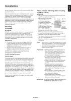
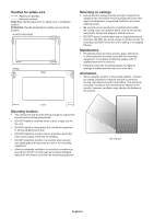
Parts Name and Functions Control Panel A Power Button ( ) Switches the power on/standby. See also page 20. B Mute Button (MUTE) Switches the audio mute on/off. C Input/Set Button (INPUT/SET) INPUT: Cycles through the available inputs when OSD menu is turned off. [DisplayPort1], [DisplayPort2], [HDMI1], [HDMI2], [HDMI3], [MP], [OPTION*], [C MODULE]*1. These are available inputs only, shown as their factory preset name. NOTE: MP is an abbreviation of Media Player. SET: Acts as a "set" button when making a selection when the OSD (On Screen Display) menu is open. *: This function depends on which Option Board you are using. *1: This input is available when the optional Raspberry Pi Compute Module Interface Board and Raspberry Pi Compute Module are installed. D Plus Button (+) Increases the audio output level when the OSD menu is turned off. Acts to move the highlighted area to the right when navigating through the OSD menu options. Acts as (+) to increase the adjustment of an OSD menu option after it has been selected with the SET button. E Minus Button (-) Decreases the audio output level when the OSD menu is turned off. Acts to move the highlighted area to the left when navigating through the OSD menu options. Acts as (-) to decrease the adjustment of an OSD menu option after it has been selected with the SET button. F Up Button ( ) Activates the OSD menu when the OSD menu is turned off. Acts as button to move the highlighted area up to select adjustment items within the OSD menu. G Down Button ( ) Activates the OSD menu when the OSD menu is turned off. Acts as button to move the highlighted area down to select adjustment items within the OSD menu. H Menu/Exit Button (MENU/EXIT) Activates the OSD menu when the OSD menu is turned off. Acts as a back button within the OSD to move to the previous OSD menu. Acts as an EXIT button to close the OSD when on the main menu. I Remote Control Sensor and Power Indicator Receives the signal from the remote control (when using the wireless remote control). See also page 14. Glows blue when the LCD monitor is in active mode*. Green and Amber blink alternately when the "SCHEDULE SETTINGS" function is enabled*1. When a component failure is detected within the monitor, the indicator will blink red or blink a combination of red and blue. * If "OFF" is selected in the "POWER INDICATOR" (see page 43), the LED will not glow when the LCD monitor is in active mode. *1 If "OFF" is selected in the "SCHEDULE INDICATOR" (see page 43), the LED will not blink. NOTE: Please refer to the POWER INDICATOR (see page 43). J Room Light Sensing Sensor Detects the level of ambient light, allowing the monitor to make automatic adjustments to the backlight setting, resulting in a more comfortable viewing experience. Do not cover this sensor. See page 43. English-10
-
 1
1 -
2
-
3
-
4
-
5
-
6
-
 7
7 -
 8
8 -
 9
9 -
 10
10 -
 11
11 -
 12
12 -
 13
13 -
 14
14 -
 15
15 -
 16
16 -
 17
17 -
18
-
19
-
20
-
21
-
22
-
23
-
24
-
25
-
26
-
27
-
28
-
29
-
30
-
31
-
32
-
33
-
34
-
35
-
36
-
37
-
38
-
39
-
40
-
41
-
42
-
43
-
44
-
45
-
46
-
47
-
48
-
49
-
50
-
51
-
52
-
53
-
54
-
55
-
56
-
57
-
58
-
59
-
60
-
61
-
62
-
63
-
64
-
65
-
66
-
67
-
68
-
69
-
70
-
71
-
72
-
73
-
74
-
75
-
76
-
77
-
78
-
79
-
80
 |
 |
