NEC V754Q Users Manual - English - Page 13
English-11, cudio IO, DisplayPort IO1/IO2, HDMI IO1/IO2/IO3, RS-232C IO D-Sub 9 pin, Remote IO, USB
 |
View all NEC V754Q manuals
Add to My Manuals
Save this manual to your list of manuals |
Page 13 highlights
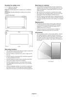
English Terminal Panel USB Upstream A AC IN Connector Connects with the supplied power cord. B Main Power Switch On/Off switch to turn main power ON/OFF. C Audio IN Audio signal input from external equipment such as a computer or player. D DisplayPort OUT Output DisplayPort signals from DisplayPort IN1. You can connect multiple monitors by using DisplayPort daisy-chain connection. See MULTI DISPLAY (page 39) and Video out (page 68). E DisplayPort IN1/IN2 DisplayPort signals input. F HDMI IN1/IN2/IN3 Digital HDMI signals input. G RS-232C IN (D-Sub 9 pin) Connect RS-232C input from external equipment, such as a computer, in order to control RS-232C functions. H Remote IN Use the optional sensor unit by connecting it to your monitor. NOTE: Do not use this connector unless specified. I microSD Card Slot microSD memory card reader for use with the Media Player (See page 23). To install the microSD card slot cover, please refer to "Installing microSD card slot cover" (See page 23). J USB Port USB1: Downstream port (USB Type-A). Connect USB devices. USB2: Upstream port (USB Type-B). Connect external equipment such as a computer. To control the monitor from connected external equipment, please use this port. USB CM1 (2A): Power supply port. USB CM2*: Service port. Please do not connect devices. * USB functionality is available when the optional Raspberry Pi Compute Module Interface Board and Raspberry Pi Compute Module are installed. USB MP: USB storage device reader for use with the Media Player. See page 22. This port is for future software upgrades. To use the Media Player, please connect USB storage device to this port (See page 19). MP is an abbreviation of Media Player. K LAN Port 1/2 (RJ-45) Connect to LAN in order to manage and control the monitor over the network. See page 48 and page 51. NOTE: Please give priority for use to LAN1. L Audio OUT Audio signal output from the AUDIO IN, DisplayPort and HDMI to an external device (stereo receiver, amplifier, etc.). NOTE: This connector is not a Headphone terminal. M Internal/External Speaker Switch : Internal speaker : External speaker. NOTE: Please turn off the monitor's main power when you use the Internal/External speaker switch. N External Speaker Terminal Audio signal output. Red terminal is plus (+). Black terminal is minus (-). NOTE: This speaker terminal is for 15 W + 15 W (8 ohm) speaker. O Internal Speaker English-11
-
 1
1 -
2
-
3
-
4
-
5
-
6
-
7
-
 8
8 -
 9
9 -
 10
10 -
 11
11 -
 12
12 -
 13
13 -
 14
14 -
 15
15 -
 16
16 -
 17
17 -
 18
18 -
19
-
20
-
21
-
22
-
23
-
24
-
25
-
26
-
27
-
28
-
29
-
30
-
31
-
32
-
33
-
34
-
35
-
36
-
37
-
38
-
39
-
40
-
41
-
42
-
43
-
44
-
45
-
46
-
47
-
48
-
49
-
50
-
51
-
52
-
53
-
54
-
55
-
56
-
57
-
58
-
59
-
60
-
61
-
62
-
63
-
64
-
65
-
66
-
67
-
68
-
69
-
70
-
71
-
72
-
73
-
74
-
75
-
76
-
77
-
78
-
79
-
80
 |
 |
