NEC VT695 VT49/490/491/590/595/695 UM - Page 70
(4) Pin Assignments of D-Sub COMPUTER Input Connector, Mini D-Sub 15 Pin Connector, Appendix
 |
UPC - 050927253607
View all NEC VT695 manuals
Add to My Manuals
Save this manual to your list of manuals |
Page 70 highlights
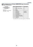
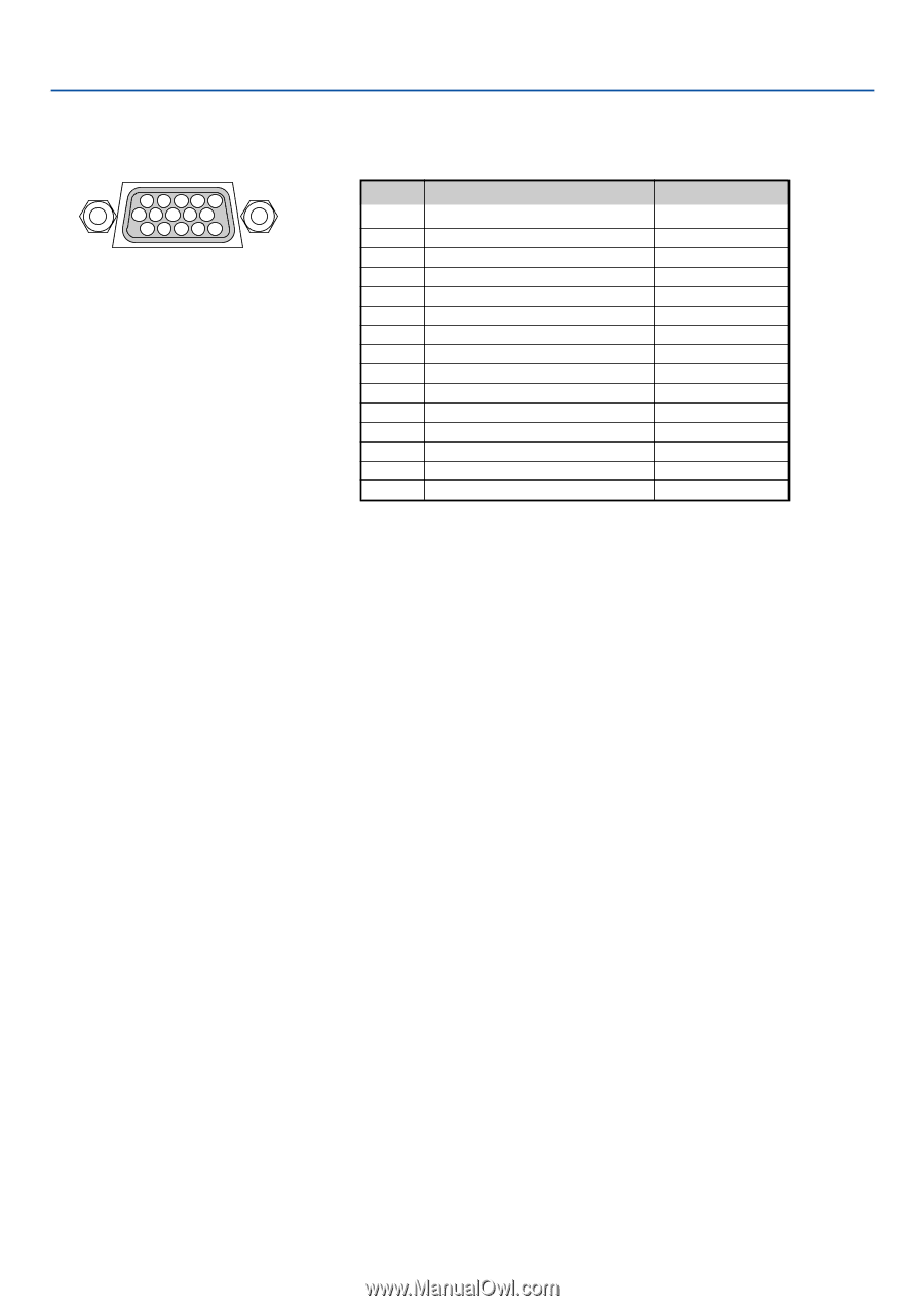
7. Appendix ᕤ Pin Assignments of D-Sub COMPUTER Input Connector Mini D-Sub 15 Pin Connector 11 12 13 14 15 6 7 8 9 10 1 23 4 5 Signal Level Video signal : 0.7Vp-p (Analog) Sync signal : TTL level Pin No. 1 2 3 4 5 6 7 8 9 10 11 12 13 14 15 RGB Signal (Analog) Red Green or Sync on Green Blue Ground Ground Red Ground Green Ground Blue Ground No Connection Sync Signal Ground No Connection Bi-directional DATA (SDA)* Horizontal Sync or Composite Sync Vertical Sync Data Clock* YCbCr Signal Cr Y Cb Cr Ground Y Ground Cb Ground * Only COMPUTER 1 input connector supported on VT695/VT595. 62
-
 1
1 -
2
-
3
-
4
-
5
-
6
-
7
-
8
-
9
-
10
-
11
-
12
-
13
-
14
-
15
-
16
-
17
-
18
-
19
-
20
-
21
-
22
-
23
-
24
-
25
-
26
-
27
-
28
-
29
-
30
-
31
-
32
-
33
-
34
-
35
-
36
-
37
-
38
-
39
-
40
-
41
-
42
-
43
-
44
-
45
-
46
-
47
-
48
-
49
-
50
-
51
-
52
-
53
-
54
-
55
-
56
-
57
-
58
-
59
-
60
-
61
-
62
-
63
-
64
-
 65
65 -
 66
66 -
 67
67 -
 68
68 -
 69
69 -
 70
70 -
 71
71 -
 72
72 -
 73
73 -
 74
74 -
 75
75 -
76
-
77
-
78
-
79
 |
 |
62
Mini D-Sub 15 Pin Connector
²
Pin Assignments of D-Sub COMPUTER Input Connector
Signal Level
Video signal : 0.7Vp-p (Analog)
Sync signal : TTL level
5
1
4
2
3
10
11
12
13 14
15
6
9
7
8
7. Appendix
* Only COMPUTER 1 input connector supported on VT695/VT595.
Pin No.
RGB Signal (Analog)
YCbCr Signal
1
Red
Cr
2
Green or Sync on Green
Y
3
Blue
Cb
4
Ground
5
Ground
6
Red Ground
Cr Ground
7
Green Ground
Y Ground
8
Blue Ground
Cb Ground
9
No Connection
10
Sync Signal Ground
11
No Connection
12
Bi-directional DATA (SDA)*
13
Horizontal Sync or Composite Sync
14
Vertical Sync
15
Data Clock*