Netgear M4250-26G4XF-PoE User Manual - Page 38
Change a LAG
 |
View all Netgear M4250-26G4XF-PoE manuals
Add to My Manuals
Save this manual to your list of manuals |
Page 38 highlights
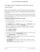
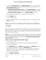
AV Line of Fully Managed Switches M4250 Series • Layer 3+4; Source: Based on the source IP address and source TCP or UDP port field in the packet. • Layer 3+4; Destination: Based on the destination IP address and destination TCP or UDP port field in the packet. • Layer 3+4; Source + Destination: Based on the source and destination IP addresses and source and destination TCP or UDP port field in the packet. The switch balances traffic on a LAG by selecting one of the links in the channel over which packets must be transmitted. The switch selects the link by creating a binary pattern from selected fields in a packet and associating that pattern with a particular link. The hash mode determines which fields in a packet the switch selects. 9. From the LAG ID menu, select an ID from 1 to 8. 10. To create a static LAG instead of a dynamic LAG, turn on the Static toggle so that it displays green and is positioned to the right. When you create a static LAG, the member ports do not transmit LACPDUs, and the LACPDUs that the member ports receive are dropped. 11. Click the Apply button. Your settings are saved. The window closes. The Link Aggregation Group page displays again. 12. To save the settings to the running configuration, at the top of the page, click the Save icon or text. Change a LAG You can change an existing LAG. To change a LAG: 1. Launch a web browser. 2. In the address field of your web browser, enter the IP address of the switch. The login page displays. 3. In the Login Name field, enter admin as the user name, in the Password field, enter your local device password, and click the AV UI Login button. The first time that you log in, no password is required. However, you then must specify a local device password to use each subsequent time that you log in. The Overview page displays. 4. Select Configure > Link Aggregation. Link Aggregation 38 Audio Video User Manual
-
 1
1 -
2
-
3
-
4
-
5
-
6
-
7
-
8
-
9
-
10
-
11
-
12
-
13
-
14
-
15
-
16
-
17
-
18
-
19
-
20
-
21
-
22
-
23
-
24
-
25
-
26
-
27
-
28
-
29
-
30
-
31
-
32
-
 33
33 -
 34
34 -
 35
35 -
 36
36 -
 37
37 -
 38
38 -
 39
39 -
 40
40 -
 41
41 -
 42
42 -
 43
43 -
44
-
45
-
46
-
47
-
48
-
49
-
50
-
51
-
52
-
53
-
54
-
55
-
56
-
57
-
58
-
59
-
60
-
61
-
62
-
63
-
64
-
65
-
66
-
67
-
68
-
69
-
70
-
71
-
72
-
73
-
74
-
75
-
76
-
77
-
78
-
79
-
80
-
81
-
82
-
83
-
84
-
85
-
86
-
87
-
88
-
89
-
90
-
91
-
92
-
93
-
94
-
95
-
96
-
97
-
98
-
99
-
100
 |
 |
