Netgear M4250-26G4XF-PoE User Manual - Page 47
Manage PoE interface settings
 |
View all Netgear M4250-26G4XF-PoE manuals
Add to My Manuals
Save this manual to your list of manuals |
Page 47 highlights
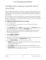
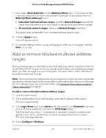
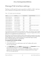
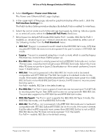
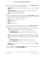
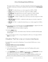
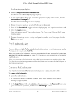
AV Line of Fully Managed Switches M4250 Series Manage PoE interface settings The Power over Ethernet (PoE) models support 8, 24, or 40 PoE+ or PoE++ interfaces with the capacities and budgets that are described in the following table. Table 1. PoE interface capacities and budgets Model PoE Ports Port Capacity Switch PoE Budget M4250-10G2F-PoE+ 8 PoE+ (802.3at) 30W 125W M4250-10G2XF-PoE+ 8 PoE+ (802.3at) 30W 240W M4250-10G2XF-PoE++ 8 PoE++ (802.3bt) 90W 720W M4250-26G4F-PoE+ 24 PoE+ (802.3at) 30W 300W M4250-26G4XF-PoE+ 24 PoE+ (802.3at) 30W 480W M4250-26G4F-PoE++ 24 PoE++ (802.3bt) 90W 1440W (with 2 power supplies) M4250-40G8F-PoE+ 40 PoE+ (802.3at) 30W 480W M4250-40G8XF-PoE+ 40 PoE+ (802.3at) 30W 960W M4250-40G8XF-PoE++ 40 PoE++ (802.3bt) 90W 2880W (with 3 power supplies) Supplied power is prioritized according to the port order, up to the total power budget of the device. For example, on an 8-port model, port 1 receives the highest PoE priority, while port 8 is relegated to the lowest PoE priority. If the power requirements for attached powered devices (PDs) exceed the total power budget of the switch, the PoE power to the device on the highest-numbered active PoE port is disabled to make sure that the devices connected to the higher-priority, lower-numbered PoE ports are supported first. To manage the PoE interface settings: 1. Launch a web browser. 2. In the address field of your web browser, enter the IP address of the switch. The login page displays. 3. In the Login Name field, enter admin as the user name, in the Password field, enter your local device password, and click the AV UI Login button. The first time that you log in, no password is required. However, you then must specify a local device password to use each subsequent time that you log in. The Overview page displays. Power over Ethernet 47 Audio Video User Manual
-
 1
1 -
2
-
3
-
4
-
5
-
6
-
7
-
8
-
9
-
10
-
11
-
12
-
13
-
14
-
15
-
16
-
17
-
18
-
19
-
20
-
21
-
22
-
23
-
24
-
25
-
26
-
27
-
28
-
29
-
30
-
31
-
32
-
33
-
34
-
35
-
36
-
37
-
38
-
39
-
40
-
41
-
 42
42 -
 43
43 -
 44
44 -
 45
45 -
 46
46 -
 47
47 -
 48
48 -
 49
49 -
 50
50 -
 51
51 -
 52
52 -
53
-
54
-
55
-
56
-
57
-
58
-
59
-
60
-
61
-
62
-
63
-
64
-
65
-
66
-
67
-
68
-
69
-
70
-
71
-
72
-
73
-
74
-
75
-
76
-
77
-
78
-
79
-
80
-
81
-
82
-
83
-
84
-
85
-
86
-
87
-
88
-
89
-
90
-
91
-
92
-
93
-
94
-
95
-
96
-
97
-
98
-
99
-
100
 |
 |