Panasonic WJHD500A WJHD500A User Guide - Page 14
Installing The Optional Network Board, The Wj-hd500a Disk Recorder.
 |
View all Panasonic WJHD500A manuals
Add to My Manuals
Save this manual to your list of manuals |
Page 14 highlights
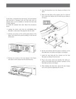
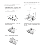
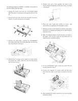
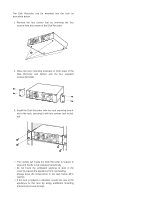
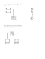
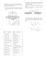
s Installing the Optional Network Board The Network Board WJ-HDB502 is installed exclusively in the WJ-HD500A Disk Recorder. 1. Unplug the power cord from the WJ-HD500A Digital Disk Recorder, or disconnect the plug from the AC outlet. 2. Remove the top cover of the Disk Recorder by removing the 11 screws, as shown in the figure. Disk Recorder WJ-HD500A 3. Remove the small plate covering the 10/100BASE-T port hole on the rear of the Disk Recorder by removing the screw shown in the figure. 5. Connect one end of the supplied flat cable to the brown-colored receptacle on the main board, as shown in the figure. Main Board Flat Cable (Supplied) 6. Place the main board and CN403 as before, and secure them by tightening the reinstalled screws. 7. Remove a screw on the bracket as shown in the figure, and then fix a supplied grounding wire by tightening the removed screw. 8. Place the Network Board on the brackets, as shown in the figure, then secure it with the grounding wire by tightening the 4 supplied screws. Network Board Grounding Wire 10/100BASE-T 4. Remove the 6 screws on the board, as shown below, disconnect the CN403, then turn over the Main Board with the front side up. CN403 Main Board Rear Panel 9. Fix the 10/100BASE-T port to the rear panel with the screw removed in step 3. 10. Connect the supplied DC power cable and the other end of the flat cable to the board, as shown in the figure. DC Power Cable (Supplied) Flat Cable (Supplied) Tighten 10/100BASE-T 11. After installing the board, secure the top cover by tightening the screws. 14
-
 1
1 -
2
-
3
-
4
-
5
-
6
-
7
-
8
-
 9
9 -
 10
10 -
 11
11 -
 12
12 -
 13
13 -
 14
14 -
 15
15 -
 16
16 -
 17
17 -
 18
18 -
 19
19 -
20
-
21
-
22
-
23
-
24
-
25
-
26
-
27
-
28
-
29
-
30
-
31
-
32
-
33
-
34
-
35
-
36
-
37
-
38
-
39
-
40
-
41
-
42
-
43
-
44
-
45
-
46
-
47
-
48
-
49
-
50
-
51
-
52
-
53
-
54
-
55
-
56
-
57
-
58
-
59
-
60
-
61
-
62
-
63
-
64
-
65
-
66
-
67
-
68
-
69
-
70
-
71
-
72
-
73
-
74
-
75
-
76
-
77
-
78
-
79
-
80
-
81
-
82
-
83
-
84
-
85
-
86
-
87
-
88
-
89
-
90
-
91
-
92
-
93
-
94
-
95
-
96
-
97
-
98
-
99
-
100
-
101
-
102
 |
 |
