Panasonic WJHD500A WJHD500A User Guide - Page 23
<Connection with the DVD Extension Unit, with HDD>, Switch Settings
 |
View all Panasonic WJHD500A manuals
Add to My Manuals
Save this manual to your list of manuals |
Page 23 highlights
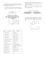
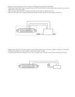
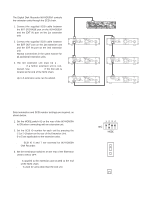
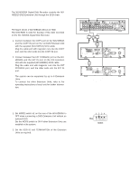
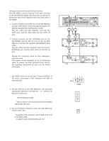
The figure shows the WJ-HDE510 with an HDD. The DVD-RAM is used for backup of the data recorded on the WJ-HD500A Digital Disk Recorder as well as for storing the data of the extension hard disk drive units in the system. 1. Connect between the COPY port on the WJ-HD500A and the COPY IN port on the 1st DVD Extension Unit with the supplied (WJ-HDE510) SCSI cable. Plug the cable end with magnetic core into the COPY port, and the other ends into the COPY IN port. 2. Connect between the EXT STORAGE port on the WJ-HD500A and the EXT IN port on the 1st DVD Extension Unit with the supplied (WJ-HDE510) SCSI cable. Plug the cable end with magnetic core into the EXT STORAGE port, and the other ends into the EXT IN port. Repeat the connection steps for any subsequent extension units. The system can be expanded by up to 6 Extension Units. To connect the other Extension Units, refer to the operating instructions of each unit for further information. EXT STORAGE Digital Disk Recorder WJ-HD500A SCSI ID=6 and 7 COPY port IN SPOT OUT EXT STORAGE COPY DATA OUT MULTISCREENOUT AUDIO CONTROL ALARM MODE 16 15 14 13 12 11 10 9 8 7 6 IN OUT 16 15 14 13 12 11 10 9 8 7 6 VIDEO CONTROL port GEN-LOCK OUT REMOTE(WV-CU50) SERIAL SIGNAL GND 10/100BASE-T 5 4 3 2 1 5 4 3 2 1 SCSI cable (supplied) SCSI cable (supplied) AC IN ON OFF POWER EXT IN COPY IN DVD Extension Unit #1 WJ-HDE510 SCSI ID=0 to 5 EXT IN EXT OUT HDD INSTALLED NOT INSTALLED COPY IN SCSI ID - 1 + TERMINATOR ON OFF G THERMAL ERROROUT NC AC IN POWER ON OFF SIGNAL GND EXT OUT EXT IN SCSI cable (supplied with Extension Unit) Terminal board EXT IN EXT OUT + - SCSI ID TERMINATOR ON OFF GND THERMAL ERROR OUT NC AC IN POWER ON OFF SIGNAL GND Extension Unit #2 WJ-HDE500/HDE505 SCSI ID=0 to 5 q Switch Settings 1. Set MODE switch #2 on the rear of the WJ-HD500A to ON when connecting a DVD Extension Unit with an optional HDD. 1 2 3 4 ON MODE 2. Set the SCSI ID for the DVD Extension Unit and each subsequent Extension Unit with the - or + selector on the rear of each Unit. 0 to 5: IDs for Extension Units. Note: SCSI ID 6 and 7 are reserved for the WJ-HD500A Digital Disk Recorder. 3. Set the termination switches on the rear of the Extension Units to ON or OFF. ON: Is applied to the extension unit located at the end of the SCSI chain. OFF: Is used for units other than the end unit. SCSI ID - 1 + ON OFF 23
-
 1
1 -
2
-
3
-
4
-
5
-
6
-
7
-
8
-
9
-
10
-
11
-
12
-
13
-
14
-
15
-
16
-
17
-
 18
18 -
 19
19 -
 20
20 -
 21
21 -
 22
22 -
 23
23 -
 24
24 -
 25
25 -
 26
26 -
 27
27 -
 28
28 -
29
-
30
-
31
-
32
-
33
-
34
-
35
-
36
-
37
-
38
-
39
-
40
-
41
-
42
-
43
-
44
-
45
-
46
-
47
-
48
-
49
-
50
-
51
-
52
-
53
-
54
-
55
-
56
-
57
-
58
-
59
-
60
-
61
-
62
-
63
-
64
-
65
-
66
-
67
-
68
-
69
-
70
-
71
-
72
-
73
-
74
-
75
-
76
-
77
-
78
-
79
-
80
-
81
-
82
-
83
-
84
-
85
-
86
-
87
-
88
-
89
-
90
-
91
-
92
-
93
-
94
-
95
-
96
-
97
-
98
-
99
-
100
-
101
-
102
 |
 |
