Panasonic WJHD500A WJHD500A User Guide - Page 21
CONNECTION WITH THE EXTENSION UNITS, SCSI Connection, Switch Setting
 |
View all Panasonic WJHD500A manuals
Add to My Manuals
Save this manual to your list of manuals |
Page 21 highlights
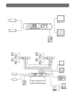
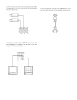
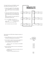
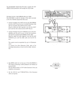
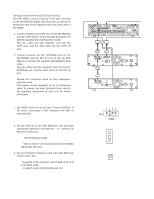
s Connection with the Extension Units q SCSI Connection The Digital Disk Recorder WJ-HD500A controls the extension units through the SCSI chain. 1. Connect the supplied SCSI cable between the EXT STORAGE port on the WJ-HD500A and the EXT IN port on the 1st extension unit. 2. Connect the supplied SCSI cable between the EXT OUT port on the 1st extension unit and the EXT IN port on the 2nd extension unit. Repeat connections in the same manner for all additional extension units. 3. The 3rd extension unit must be a WJHDE505 if a further extension unit is connected. Use WJ-HDE500 if the 3rd unit is located at the end of the SCSI chain. Up to 6 extension units can be added. SCSI Cable SCSI Cable SCSI Cable Digital Disk Recorder WJ-HD500A SCSI ID = 6 and 7 IN SPOT OUT EEXXTT SSTTOORRAAGGEE COPY DATA OUT MULTISCREENOUT AUDIO CONTROL ALARM MODE 16 15 14 13 12 11 10 9 8 7 6 IN OUT 16 15 14 13 12 11 10 9 8 7 6 VIDEO GEN-LOCK OUT REMOTE(WV-CU50) SERIAL SIGNAL GND 10/100BASE-T 5 4 3 2 1 5 4 3 2 1 AC IN ON OFF POWER EXT IN EXT OUT + - SCSI ID TERMINATOR ON OFF GND THERMAL ERROR OUT NC Extesion Unit #1 WJ-HDE500 SCSI ID = 5 AC IN POWER ON OFF SIGNAL GND EXT IN EXT OUT + - SCSI ID TERMINATOR ON OFF GND THERMAL ERROR OUT NC Extesion Unit #4 WJ-HDE500 SCSI ID = 2 AC IN POWER ON OFF SIGNAL GND SCSI Cable SCSI Cable EXT IN EXT OUT + - SCSI ID TERMINATOR ON OFF GND THERMAL ERROR OUT NC Extesion Unit #2 WJ-HDE500 SCSI ID = 4 AC IN POWER ON OFF SIGNAL GND EXT IN EXT OUT + - SCSI ID TERMINATOR ON OFF GND THERMAL ERROR OUT NC Extesion Unit #3 WJ-HDE500 or WJ-HDE 505* SCSI ID = 3 AC IN POWER ON OFF SIGNAL GND SCSI Cable EXT IN EXT OUT + - SCSI ID TERMINATOR ON OFF GND THERMAL ERROR OUT NC Extesion Unit #5 WJ-HDE500 SCSI ID = 1 AC IN POWER ON OFF SIGNAL GND EXT IN EXT OUT + - SCSI ID TERMINATOR ON OFF GND THERMAL ERROR OUT NC Extesion Unit #6 WJ-HDE500 SCSI ID = 0 AC IN POWER ON OFF SIGNAL GND * Use a WJ-HDE505 for the 3rd unit position if additional units are installed. Use a WJ-HDE500 if the 3rd position is the end of the SCSI chain. q Switch Setting Data termination and SCSI number settings are required, as shown below. 1. Set the MODE switch #2 on the rear of the WJ-HD500A to ON when connecting with an extension unit. 2. Set the SCSI ID number for each unit by pressing the [-] or [+] button on the rear of the Extension Unit. 0 to 5 are applicable to the extension units. Note: SCSI ID 6 and 7 are reserved for WJ-HD500A Disk Recorder. 3. Set the termination switches on the rear of the Extension Units to ON or OFF. ON: Is applied to the extension unit located at the end of the SCSI chain. OFF: Is used for units other than the end unit. 1 2 3 4 ON MODE SCSI ID - 1 + TERMINATOR ON OFF 21
-
 1
1 -
2
-
3
-
4
-
5
-
6
-
7
-
8
-
9
-
10
-
11
-
12
-
13
-
14
-
15
-
 16
16 -
 17
17 -
 18
18 -
 19
19 -
 20
20 -
 21
21 -
 22
22 -
 23
23 -
 24
24 -
 25
25 -
 26
26 -
27
-
28
-
29
-
30
-
31
-
32
-
33
-
34
-
35
-
36
-
37
-
38
-
39
-
40
-
41
-
42
-
43
-
44
-
45
-
46
-
47
-
48
-
49
-
50
-
51
-
52
-
53
-
54
-
55
-
56
-
57
-
58
-
59
-
60
-
61
-
62
-
63
-
64
-
65
-
66
-
67
-
68
-
69
-
70
-
71
-
72
-
73
-
74
-
75
-
76
-
77
-
78
-
79
-
80
-
81
-
82
-
83
-
84
-
85
-
86
-
87
-
88
-
89
-
90
-
91
-
92
-
93
-
94
-
95
-
96
-
97
-
98
-
99
-
100
-
101
-
102
 |
 |
