Panasonic WVCS564 WVCS564 User Guide - Page 41
Installation
 |
View all Panasonic WVCS564 manuals
Add to My Manuals
Save this manual to your list of manuals |
Page 41 highlights
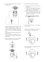
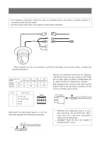
INSTALLATION Precautions • The following steps of installation and connection should be taken by qualified service personnel or system installers and should conform to all local codes. • Make sure to switch the camera off before installation and connection. • Do not install the camera near the air outlet of an air conditioner. 1. Disassembling the Camera (1) Loosen the fixing screw to separate the camera mounting base and the camera. Push up the screwdriver once before removing the screw. (2) Turn the camera mounting base approximately 15 degrees counterclockwise and remove the base from the camera. 2. Setting the Switches There are two DIP switches on the camera: an 8-bit switch and a 4-bit switch. The 8-bit DIP switch is used in both ways to return to the factory default settings and to specify the unit number. The 4-bit DIP switch selects termination ON/OFF and half/full duplex selection for RS485 communications. Switch settings are read in to the camera when the power is turned on. Make sure to turn it off, then turn it back on after changing the switch settings. Switch positions and functions are shown below. Camera mounting base Camera mounting base Fixing screw Loosen and push Camera Turn 15° Then 15° Remove from the camera Camera mounting base SW 1 ON SW 2 ON 12345678 1234 RS485 Parameter Setup The selected protocol, communication parameters, and set unit numbers are read into the camera when power is switched on. 1. Switch off the camera. 2. Set the switch according to the function shown in the table. 3. Switch on the camera to read in the changed switch settings. 4. Switch off the camera. 5. Set the unit number with the DIP switch (see next page). 6. Switch on the camera to read in the changed switch settings. Note: The changed communication parameters are displayed on the RS485 SETUP menu after the camera has been switched on. Switch position ON Returns to the factory default settings. 1234 5678 Parameter selection Switch position Baud rate Data bit Parity check Stop bit ON 19 200 8 None 1 12345678 ON 9 600 8 None 1 12345678 ON 4 800 8 None 1 12345678 43
-
 1
1 -
2
-
3
-
4
-
5
-
6
-
7
-
8
-
9
-
10
-
11
-
12
-
13
-
14
-
15
-
16
-
17
-
18
-
19
-
20
-
21
-
22
-
23
-
24
-
25
-
26
-
27
-
28
-
29
-
30
-
31
-
32
-
33
-
34
-
35
-
 36
36 -
 37
37 -
 38
38 -
 39
39 -
 40
40 -
 41
41 -
 42
42 -
 43
43 -
 44
44 -
 45
45 -
 46
46 -
47
-
48
-
49
-
50
-
51
-
52
 |
 |
