Panasonic WVCS564 WVCS564 User Guide - Page 46
Connections
 |
View all Panasonic WVCS564 manuals
Add to My Manuals
Save this manual to your list of manuals |
Page 46 highlights
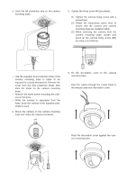
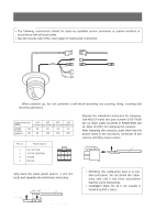
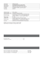
CONNECTIONS Precautions • The following connections should be made by qualified service personnel or system installers in accordance with all local codes. • See the reverse side of the cover page for mains lead connection. 24 V AC Data port Video output Not used 24 V AC cable RS485 cable Coaxial cable To VIDEO IN BNC plug (CAMERA IN) BNC plug Not used ✻ The coaxial cable length (RG-59/U, BELDEN 9259) for the connection is up to 900 meters (3 000 ft.) Note: When powered up, the unit performs a self-check (including one panning, tilting, zooming and focusing operation). • 24 V AC Power Supply Connection Recommended wire gauge sizes for 24 V AC line Copper wire size #24 #22 #20 #18 (AWG) (0.22mm2) (0.33mm2) (0.52mm2) (0.83mm2) Length (m) 20 of cable (approx.) (ft) 65 30 45 75 100 160 260 Accessory Connector Information Prepare the individual conductors for clamping. Use MOLEX band tool part number 57027-5000 (for UL-Style Cable UL1015) or 57026-5000 (for UL-Style UL1007) for clamping the contacts. After clamping the contacts, push them into the proper holes in the accessory connector of this camera until they snap in place. Pin no. Power source 1 24 V AC LIVE 2 24 V AC NEUTRAL 3 Ground 4 Not use 43 21 UUpp CCoonntatacct t WWiriere How to Assemble the Cable with the Accessory Connector Strip back the cable jacket approx. 3 mm (0.1 inch) and separate the individual conductors. CCoonnttaacctt AApppprrooxx.. 33 mmmm ((00..11 iinncchh)) UUpp A Insert WWiriree IInnsseert the wwiirreeuunntitlilAAppoossititoionn aanndd ccllaamp the connttaaccttss.. CAUTIONS • Shrinking the cable-entry seal is a one- time procedure. Do not shrink the cableentry seal until it has been ascertained that the unit is functioning. • CONNECT THIS TO 24 V AC CLASS 2 POWER SUPPLY ONLY. 48
-
 1
1 -
2
-
3
-
4
-
5
-
6
-
7
-
8
-
9
-
10
-
11
-
12
-
13
-
14
-
15
-
16
-
17
-
18
-
19
-
20
-
21
-
22
-
23
-
24
-
25
-
26
-
27
-
28
-
29
-
30
-
31
-
32
-
33
-
34
-
35
-
36
-
37
-
38
-
39
-
40
-
 41
41 -
 42
42 -
 43
43 -
 44
44 -
 45
45 -
 46
46 -
 47
47 -
 48
48 -
 49
49 -
 50
50 -
 51
51 -
52
 |
 |
