Panasonic WVCS564 WVCS564 User Guide - Page 44
Assemble the Camera, RS485 Setting, Top Cable Exit, Notes, Precaution, Sideway Cable Exit
 |
View all Panasonic WVCS564 manuals
Add to My Manuals
Save this manual to your list of manuals |
Page 44 highlights
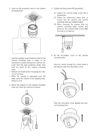
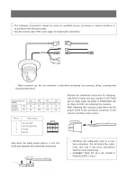
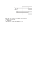
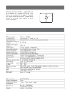
RS485 Setting The 4-bit DIP switch in used for SW 2 RS485 termination. ON 1234 Switch position BP 1 ON OFF Function Termination ON Termination OFF * BP 2 BP 3 BP 4 Function Switch ON ON ON Half duplex (2 line) position OFF OFF OFF Full duplex (4 line) * Notes: • Defaults are marked with *. • BP stands for Bit Position. • Daisy chain connection is not available for Full Duplex. (Only for Panasonic's system controllers) 3. Assemble the Camera Reverse the disassembly procedure. Take care not to cut any cables. Precaution Be sure to select a ceiling board strong enough to support 4 times the total weight of the camera. a. Sideway Cable Exit Prepare a cutout in the diecast case and decoration cover as shown in the following figures. Cutout in Diecast Case Note: Remove sharp edges to protect the cables. b. Top Cable Exit Prepare a hole in the ceiling board to run the cables. 1. Mark the mounting holes on the ceiling, using the removed camera mounting base as a template. Marking Cutout in Decoration Cover 46 2. Fix the camera mounting base to the ceiling with four screws (not provided, M4).
-
 1
1 -
2
-
3
-
4
-
5
-
6
-
7
-
8
-
9
-
10
-
11
-
12
-
13
-
14
-
15
-
16
-
17
-
18
-
19
-
20
-
21
-
22
-
23
-
24
-
25
-
26
-
27
-
28
-
29
-
30
-
31
-
32
-
33
-
34
-
35
-
36
-
37
-
38
-
 39
39 -
 40
40 -
 41
41 -
 42
42 -
 43
43 -
 44
44 -
 45
45 -
 46
46 -
 47
47 -
 48
48 -
 49
49 -
50
-
51
-
52
 |
 |
