Panasonic WVCS574 WVCS574 User Guide - Page 11
DIP SWITCH SETTINGS, Communication Parameters (DIP Switch 2)
 |
View all Panasonic WVCS574 manuals
Add to My Manuals
Save this manual to your list of manuals |
Page 11 highlights
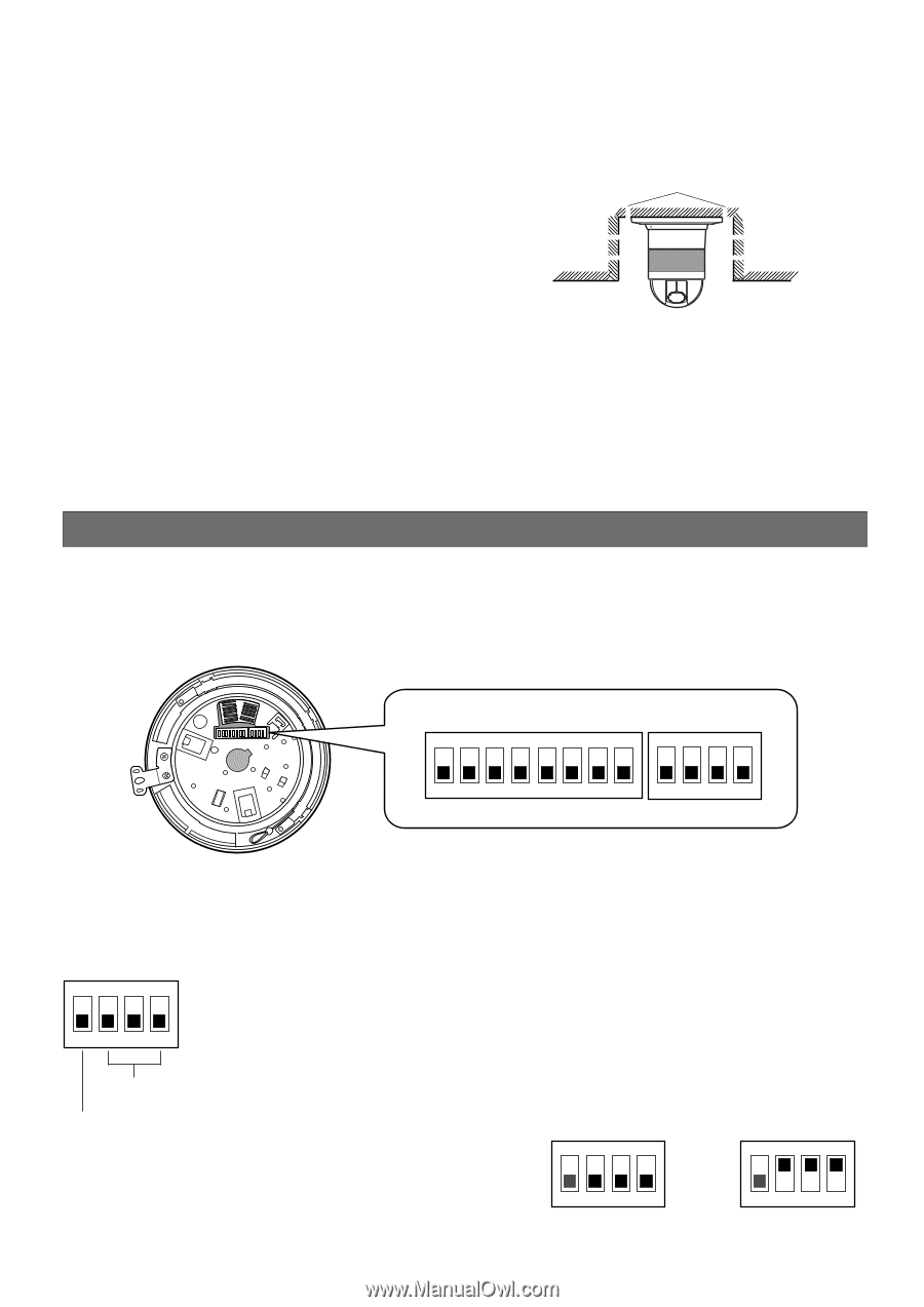
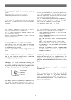
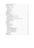
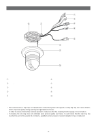
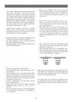
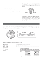
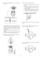
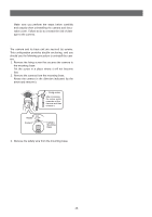
Important: Before setting up the camera for a configuration where the camera's RS485 data port is used for camera control (pan, tilt, etc.) by the system controller, the camera's DIP switches must be configured to specify the unit number and communication parameters. (This page) If DIP switch setting is not performed, the system controller control will not be possible and camera setup will have to be performed again. Be sure to check the DIP switch settings before setting up the camera. ■ Heat radiation The surface of the camera radiates heat. Ventilation holes should be provided when installing the camera in an enclosed ceiling or confined location where heat can build up. Ventilation holes ■ Beware of high humidity. If the camera is installed when humidity is very high, moisture may collect in the camera and cause the dome to become foggy. If the dome becomes foggy, remove it when the humidity is low and eliminate the moisture inside the camera, and then replace the dome. (page 9) DIP SWITCH SETTINGS In a configuration where the camera's RS485 data port is used for camera control (pan, tilt, etc.) by the system controller, the camera's DIP switches must be configured to specify the unit number and communication parameters. The camera mounting base needs to be removed to access the DIP switches. See steps 1 to 3 on page 16 for information about how to remove the camera mounting base. DIP Switch 1 ON DIP Switch 2 ON 12345678 1234 ■ Communication Parameters (DIP Switch 2) The factory default settings of these DIP switches are all OFF. ON 1234 Switch 1: Terminator (Internal Termination Resistance) Set it to ON in the following situations. When only one camera is connected. When only one camera is connected via a daisy chain over a long distance. Communication Parameters Terminator Switches 2 through 4: Communication Parameters This setting toggles between 2-line and 4-line communication. Use these switches to select the communication protocol being used. ON ON -11- 1234 4-line Communication 1234 2-line Communication
-
 1
1 -
2
-
3
-
4
-
5
-
 6
6 -
 7
7 -
 8
8 -
 9
9 -
 10
10 -
 11
11 -
 12
12 -
 13
13 -
 14
14 -
 15
15 -
 16
16 -
17
-
18
-
19
-
20
-
21
-
22
-
23
-
24
-
25
-
26
-
27
-
28
-
29
-
30
-
31
-
32
-
33
-
34
-
35
-
36
-
37
-
38
-
39
-
40
-
41
-
42
-
43
-
44
-
45
-
46
-
47
-
48
-
49
-
50
-
51
-
52
-
53
-
54
-
55
-
56
-
57
-
58
-
59
-
60
 |
 |