Panasonic WVCS574 WVCS574 User Guide - Page 18
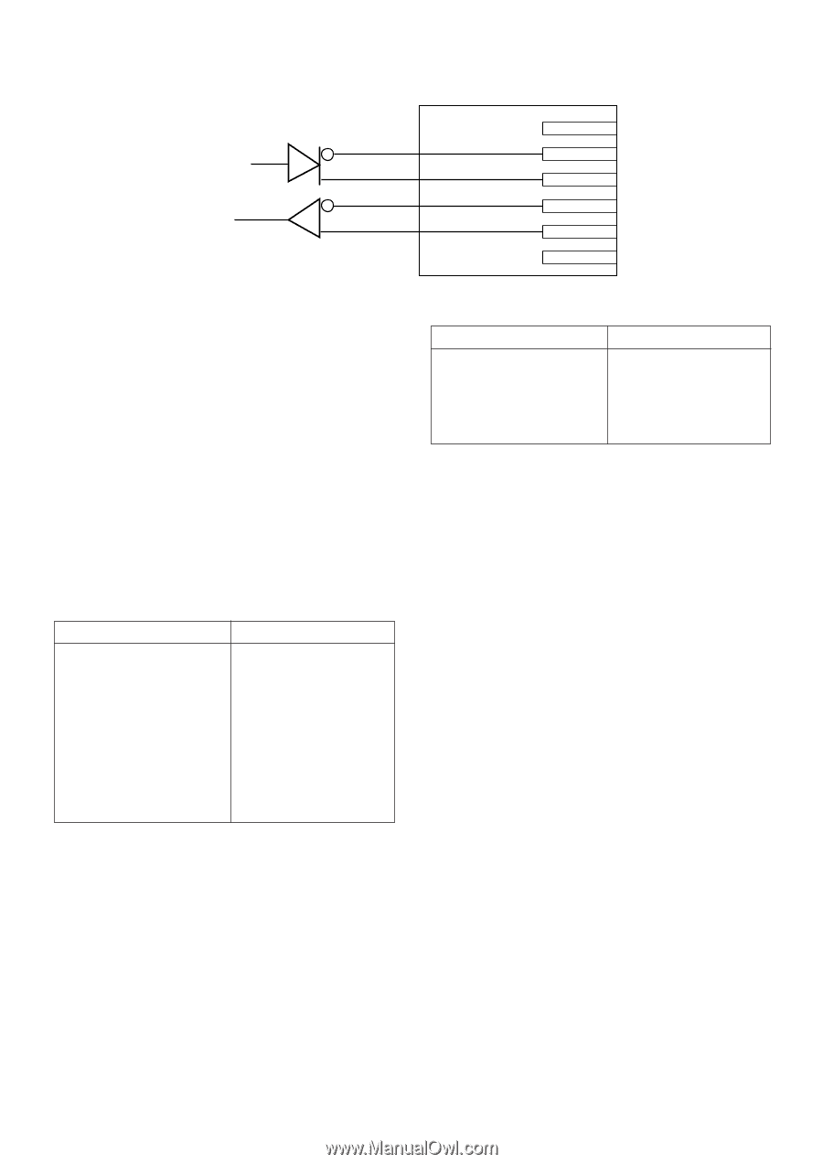
Black, Brown, Orange, Yellow, Light blue or green, Purple, Wire color, Function, White
 |
View all Panasonic WVCS574 manuals
Add to My Manuals
Save this manual to your list of manuals |
Page 18 highlights
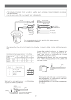
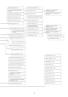
• RS485 Connection Data transmission Data reception Red Orange Yellow Green T (B) T (A) R (B) R (A) Note: Use the cable that is described below for RS485 site communication. • Shielded, twisted pair cable • Low impedance • Wire gauge size is thicker than AWG #22 (0.33 mm2). • ALARM IN Connections An 8-pin and a 4-pin harness are supplied with the camera as standard accessories. Connect external sensors to this connector. Input specifications are lowactive, non-voltage contact (ON when active) or open collector (Low when active). The table below shows wire colors versus pin functions. Alarm IN (8-pin) Wire color Function Black Brown Red Orange Yellow Light blue or green Blue Purple IN 1 GND IN 2 GND IN 3 GND IN 4 GND Alarm OUT (4-pin) Wire color Function Gray White Pink Yellow green or light blue OUT 1 GND OUT 2 GND Note: Use a relay if the voltage or current of the connected device exceeds the ratings. • ALARM OUT Connections Connect an external device, for example, a buzzer or lamp, to this connector. Output specifications are lowactive, open-collector and a drive capacity of 16 V DC 100 mA maximum. The table below shows wire colors versus pin functions. -18-
-
 1
1 -
2
-
3
-
4
-
5
-
6
-
7
-
8
-
9
-
10
-
11
-
12
-
 13
13 -
 14
14 -
 15
15 -
 16
16 -
 17
17 -
 18
18 -
 19
19 -
 20
20 -
 21
21 -
 22
22 -
 23
23 -
24
-
25
-
26
-
27
-
28
-
29
-
30
-
31
-
32
-
33
-
34
-
35
-
36
-
37
-
38
-
39
-
40
-
41
-
42
-
43
-
44
-
45
-
46
-
47
-
48
-
49
-
50
-
51
-
52
-
53
-
54
-
55
-
56
-
57
-
58
-
59
-
60
 |
 |