Pfaff 1245 - 1246 Owner's Manual - Page 39
Adjustment, Tools, gauges, other, accessories, adjusting, Notes, Abbreviations
 |
View all Pfaff 1245 - 1246 manuals
Add to My Manuals
Save this manual to your list of manuals |
Page 39 highlights
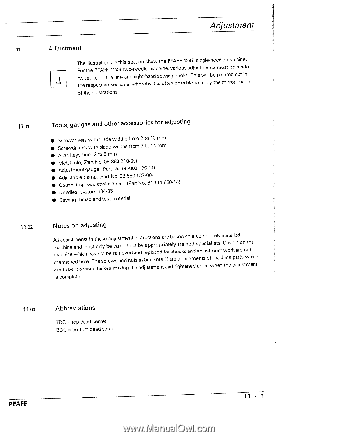
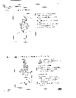
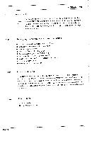
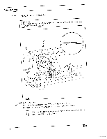
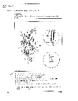
Adjustment 11 Adjustment The illustrations in this section show the PFAFF 1245 single-needle machine. Fttwhoerictrehe,esip.Pee.FcAttoiFvFtehes1e2lc4etf6ito-tnwasno,d-wnreihgeehdrtel-ebhaymndiat cishseiownfeit,negnvahprioooosusksisb.aledTjhtuoisstawmpiplellnybtesthmpeouminsittrerbdoeromiumtaadingee of the illustrations. 11.01 Tools, gauges and other accessories for adjusting • Screwdrivers with blade widths from 2 to 10 mm • Screwdrivers with blade widths from 7 to 14 mm • Allan keys from 2 to 6 mm • Metal rule, (Part No. 08-880 218-00) • Adjustment gauge, (Part No. 08-880 136-14) • Adjustable clamp, (Part No. 08-880 137-00) • Gauge, (top feed stroke 7mm) (Part No.61-111 630-14) • Needles, system 134-35 • Sewing thread and test material 11.02 Notes on adjusting Ammamlrlaaeecacnthdhtoiiijonnubneesetemawdlnohedhoincesmthresenu.hiensaTdtvthohebeneetlssoyfceorbbreaeeewdmrcjseuaamrsakrtniomiendvdgeenndotuthutaetisnnbadisnytdrrjbuaeurcppsatlpticamorkconeeesptdnsrtaifr(aoae)tnreadbclryahetsiegtaecrhtdkattasieoncnnaehendmadd cesaapongdmetajscuipnisoaltfewlmitmeshetleansycn.thiCwntihnsooteevarkleaplredaasdjrruteossnntwmothhteeincht is complete. 11.03 Abbreviations TDC top dead center BDC bottom dead center PFAFF 11 - 1
-
 1
1 -
2
-
3
-
4
-
5
-
6
-
7
-
8
-
9
-
10
-
11
-
12
-
13
-
14
-
15
-
16
-
17
-
18
-
19
-
20
-
21
-
22
-
23
-
24
-
25
-
26
-
27
-
28
-
29
-
30
-
31
-
32
-
33
-
 34
34 -
 35
35 -
 36
36 -
 37
37 -
 38
38 -
 39
39 -
 40
40 -
 41
41 -
 42
42 -
 43
43 -
 44
44 -
45
-
46
-
47
-
48
-
49
-
50
-
51
-
52
-
53
-
54
-
55
-
56
-
57
-
58
-
59
-
60
-
61
-
62
-
63
-
64
-
65
-
66
-
67
-
68
-
69
-
70
-
71
-
72
-
73
-
74
-
75
-
76
-
77
-
78
 |
 |