Pfaff 1245 - 1246 Owner's Manual - Page 65
Requirement
 |
View all Pfaff 1245 - 1246 manuals
Add to My Manuals
Save this manual to your list of manuals |
Page 65 highlights
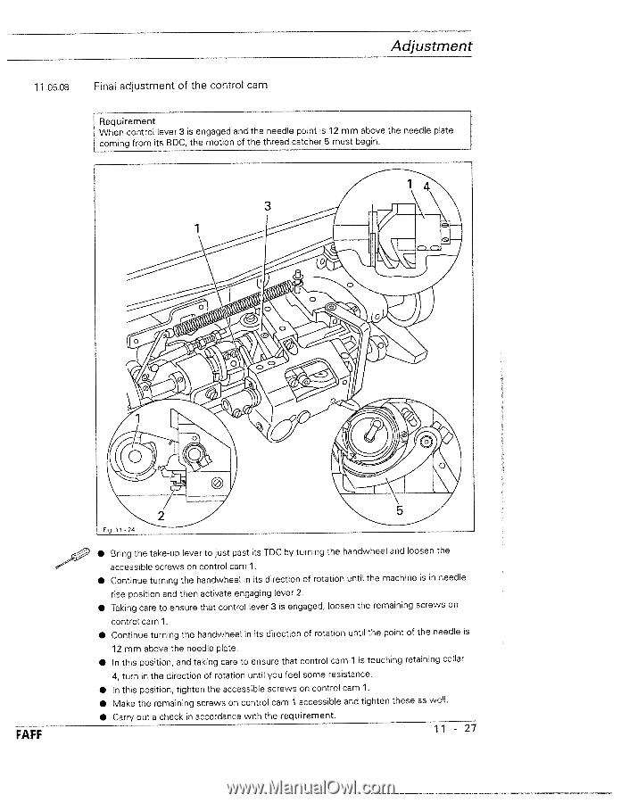
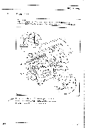
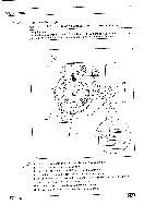
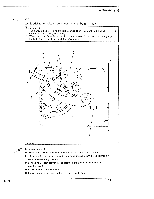
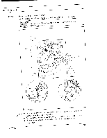
Adjustment 11 .05.08 Final adjustment of the control cam Requirement When control lever 3 is engaged and the needle point is 12 mm above the needle plate coming from its BDC, the motion of the thread catcher 5 must begin. /Th\ 3 cW I 4-'N Jc / FAFF Fg 1124 • Bring the take-up lever to just past its TDC by turning the handwheel and loosen the accessible screws on control cam 1. • Continue turning the handwheel in its direction of rotation until the machine is in needle rise position and then activate engaging lever 2. • Taking care to ensure that control lever 3 is engaged, loosen the remaining screws on control cam 1. • Continue turning the handwheel in its direction of rotation until the point of the needle is 12 mm above the needle plate. • In this position, and taking care to ensure that control cam 1 is touching retaining collar 4, turn in the direction of rotation until you feel some resistance. • In this position, tighten the accessible screws on control cam 1. • Make the remaining screws on control cam 1 accessible and tighten these as well. • Carry out a check in accordance with the requirement. 11 - 27
-
 1
1 -
2
-
3
-
4
-
5
-
6
-
7
-
8
-
9
-
10
-
11
-
12
-
13
-
14
-
15
-
16
-
17
-
18
-
19
-
20
-
21
-
22
-
23
-
24
-
25
-
26
-
27
-
28
-
29
-
30
-
31
-
32
-
33
-
34
-
35
-
36
-
37
-
38
-
39
-
40
-
41
-
42
-
43
-
44
-
45
-
46
-
47
-
48
-
49
-
50
-
51
-
52
-
53
-
54
-
55
-
56
-
57
-
58
-
59
-
 60
60 -
 61
61 -
 62
62 -
 63
63 -
 64
64 -
 65
65 -
 66
66 -
 67
67 -
 68
68 -
 69
69 -
 70
70 -
71
-
72
-
73
-
74
-
75
-
76
-
77
-
78
 |
 |